|
|
Add Component  / Add a Duplicate Copy
  / Add This Component / Add Electrode
 : Options and Results


Access: Open this function from one of the following locations:
Add Component
-
Click
in the toolbar. -
Select Assembly > Main Tools > Add Component from the menu bar.
-
When no geometry is selected, right-click in the graphics window to display the Graphics Area popup menu and select Add Component.
Add a Duplicate Copy
-
Click
in the toolbar. -
Select Assembly > Main Tools > Add a Duplicate Copy from the menu bar.
-
Select Add a Duplicate Copy in the popup menu when no geometry is selected.
-
Select Add a Duplicate Copy from the Mold Design Guide Toolbar.
Add This Component
-
Right-click on a sub-assembly, folder, or a component in the Assembly Tree or on a component in the Graphics Area to display the popup menu and select Add This Component.
Add Electrode
-
Select Electrode > Add Electrode > Add Electrode from the menu bar.
Function variations
|
Add Component |
Add a component to the assembly / sub-assembly. |
|
Add a Duplicate Copy |
Add a component that is a duplicate copy of an existing component, to the assembly / sub-assembly. This function is used to add mechanisms, assemblies, and other components that you have used in previous projects. Add a Duplicate Copy is similar to Add Component, however, Add a Duplicate Copy creates a free copy of the component and allows you to add it to your current assembly without affecting the original assembly. |
|
Add This Component |
Add a preselected component to the assembly / sub-assembly. |
|
Add Electrode |
Add an existing electrode part. |
Notes:
-
Any connections that are created automatically when a part is added will be written under the added part only.
-
Undo operations are available after adding a component.
Required Step 1 
Add This Component—You must pre-select a component (in the Assembly Tree or the Graphics Area) before usingusing the function, which completes Required Step 1.
Add Component, Add a Duplicate Copy:
-
Drag and drop one or more components into the assembly which completes Required Step 1.
-
Add one or more components to an assembly or sub-assembly. The Cimatron Explorer is displayed. Select one or more components to be added (this includes external format files).
-
External format files (for which you have a license to read) can be opened or added directly to a Cimatron assembly without importing them. Set the Filter on the Cimatron Explorer to External File Formats or All Types to display the external format files.
For more on directly adding external format files to a Cimatron assembly, see Import (Drag & Drop/Direct Import) External Format File.
Required Step 2 
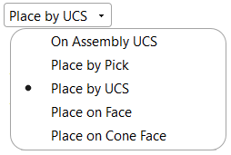
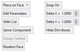
- Place the component. The following options are displayed, depending on the type of entity to be added (a component or an assembly).
Component
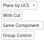
If a cutting object exists the With/ Without Cut toggle option is displayed.
For the Add This Component function, additional options are displayed.
There are several placing options.
If a catalog component is added the Edit Parameters option is displayed.
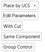
If a Catalog component is being added, the Edit Parameters parameter is also displayed.
Parameters
With each placing option, a number of parameters may be displayed depending on the circumstances.
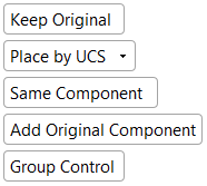
Keep Original /
Delete OriginalThis option is displayed when using Add This Component.
Keep Original – Keep the originally selected part/assembly in the assembly.
Delete Original – Delete the originally selected part/assembly from the assembly (only the selected instance is deleted).
In this case, a warning message is displayed prompting your confirmation to delete the component.
If you select Yes to confirm the deletion, the part/assembly is deleted.
If you select No to cancel the deletion, the add operation continues without deleting the original part (as if you selected Keep Original). If the original part was used to cut another part, a standard cut warning message is displayed.
Notes:
-
The Add Component toggle options Same Component / Different Component are not affected by the Keep Original / Delete Original option. For example, when working with Delete Original and also with Different Component, the added part will be different.
-
When editing the results of this function using Edit Add, the toggle option Keep Original / Delete Original is not displayed.
Edit Parameters
This parameter is displayed if the component being added is a Catalog part and is used to select a different set of predefined component parameters from the Catalog parameter table (see the Edit Parameters example).
With Cut /
Without CutThis toggle option is displayed if the component being added has a cutting object (see With Cut / Without Cut).
Same Component / Different Components
This toggle option is displayed in all the placing options (see Same Component/Different Components). Both components are added with the same channel properties, either with the same Delta or with no channel.
Add Original Component /
Add as a Duplicate CopyThis toggle option is displayed when using the function Add This Component and when the toggle option Same Component is selected. This allows you to add the original component or add a duplicate component of it.
Add Original Component – Add the component as an original component, not as a copy.
Add as a Duplicate Copy – Create a single duplicate copy of the added component and then use instances of it in all locations.
This is useful when you want to add several instances of an existing component – you want all of them to be instances of a single part but you don’t want it to be the original part, but rather a copy of it.
Group Control / Individual Control
This toggle option is displayed if multiple instances of a component are added, providing Group or Individual control over the parameters of each instance. See Group Control / Individual Control.
This toggle option is displayed in the Place by UCS, Place on Face, and Place on Cone Face placing options.
Reselect Face
Use this parameter to change the face to which components are being added. Select Reselect Face and then pick the required face.
This toggle option is displayed in the Place on Face placing option.
Snap On /
Snap OffSnap On is used to snap to a location when positioning a component. If Snap On is selected and the Grid mode is on (the grid is displayed), additional parameters to those shown above are displayed.
This toggle option is displayed in the Place on Face placing option.
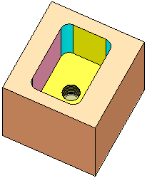
Note: If a component that has a cutting object is added to an assembly using the With Cut parameter and if the Transfer Color checkbox (in the Entity Properties dialog) is checked, then the component's attributes (colors, hole, and thread properties) are transferred to the active object.
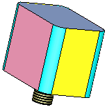
ExampleExampleAssembly
Component to be added
Result using "With Cut"
The added component's attributes (colors, hole, and thread properties) are transferred to the active object.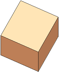
Placing options
-
- Press MMB to <exit><exit> when finished.
- Click OKOK
 or ApplyApply
 in the Feature Guide to complete the function.
Optional Step 1 
- Set the offset and rotation parameters. The following options are available.
Parameters
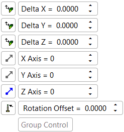
Delta X
Delta Y
Delta ZSet the Offset parameters as required.
Adjacent to each parameter is a toggle button that determines whether to apply the X, Y, Z Delta on the relevant direction of the placement face UCS or that of the added part UCS.

Apply the X, Y, Z Delta on the relevant direction of the placement face UCS. For example, selecting this toggle option adjacent to the Delta X parameter would apply the Delta X value to the X direction of the placement face UCS.

Apply the X, Y, Z Delta on the relevant direction of the added part UCS. For example, selecting this toggle option adjacent to the Delta X parameter would apply the Delta X value to the X direction of the added part UCS.
X Axis
Y Axis
Z AxisSet the Rotation parameters as required.
The direction arrow axis can be configured for each parameter.
Rotation Offset
Set the rotation offset distance to rotate around a point at a distance from the placement plane. This offset determines the distance from the placement plane to the rotation axis point, normal to the add plane.
ExampleExample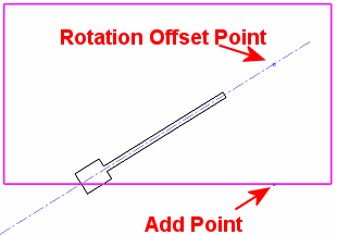
Click the button adjacent to the parameter to define the offset value by picking a cylindrical face or a point. The selected point distance is displayed in the offset value.
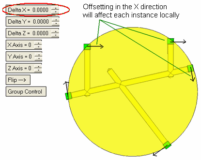
Group Control
When adding more than one instance of a component, Group Control provides Group or Individual control over the parameters of each instance.
Notes:
-
Offsetting and rotating items placed on a cone face will affect every instance locallyevery instance locally according to the position of its UCS.
-
To deselect the locating face or cancel the location operation, switch to another locating option and then return and select the new face.
-
Optional Step 2 
-
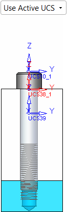
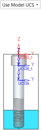
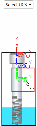
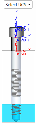
Pick a UCS on the added component to position the component. The following options are available:
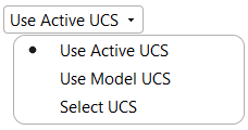
Note: When adding a part to an assembly (using the Add Component or Add From Catalog functions), use the option Using Model UCS to ensure that the parts are placed as they were created in the correct position. The default option is Using Active UCS.
The selected reference UCS is highlighted in red.
Optional Step 3 
-
Select the parts to be cut in the Cut Manager. This step is used to manually control which parts are to be cut.
- Click OKOK or ApplyApply in the Feature Guide to complete the function.
Notes:
-
For the Assembly Add operations (Add Component, Add Duplicate, Add This Component, Add External Catalog Part, Add From Catalog, Add New Part, and Add New Sub-Assembly), the following is relevant:
-
-
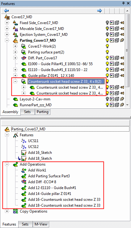
In the Feature Tree, in addition to the feature name indicating the type of operation performed, the part name of the added component is also displayed in the feature name.
-
The feature created by the Add operation is listed in the Feature Tree under the Add Operations branch of the relevant assembly.
-
In addition to the usual method of editing a feature, this Add operation can also be edited using the Edit Add function.
-
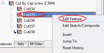
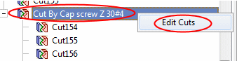
When adding multiple instances to an assembly using an Add operation, the Feature Tree shows only one combined cut operation. The individual cut operations for each component can be viewed under the leaf for the combined cut operation in the tree. The Add operation can also be edited directly from the Feature Tree of the part that was cut, rather than from the Assembly Tree.
ExamplesExamplesNote the one combined cut operation feature at the end of tree.
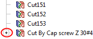
When expanded, you can edit each cut operation separately.
You can also re-enter the Edit Add operation by editing the combined cut feature.
-
The component(s) is added with the same units as those of the main assembly.
-
-
|
When complete, the Assembly and Feature Trees are updated as follows:
|
|

|