|
|
Send To AutoForm: Dialog 

Access: Open this function from one of the following locations:
-
Select Die Design > AutoForm > Send To AutoForm from the menu bar. Select the required function.
-
Select Send To AutoForm from the following Die Design Guides: Die Tool Design Guide (Progressive).
Send die design data to AutoForm for analysis. Data preparation for AutoForm is an important step for executing a successful and accurate simulation.
The Send to AutoForm function is an interactive guided dialog that helps in selecting the required information (for example, Pilot, Trimming, Forming, and Cams) for AutoForm integration directly from the Strip. For a safer and faster selection, some entities are automatically selected by the tool and some require manual selection.
See Send To AutoForm for additional information.
In Cimatron, open the Send To AutoForm function and attach geometry to relevant sets:
-
The Send To AutoForm dialog is displayed.
-
Assign (automatically) general data (such as thickness and progression/pitch).
-
Assign/Map (manually) any other geometry and parameters required to prepare AutoForm template items.
-
Add additional reference geometry if required. In the AutoForm ProgSim Simulation tool, new geometry cannot be created, only the existing (imported) geometry is used.
-
Export the data to AutoForm.
Important: All data is exported to AutoForm in MM and not according to the units of the project.
The Send To AutoForm dialog is displayed.
Attach geometries to appropriate sets and define the required parameters that will be used in AutoForm. The assign and mapping process can be done automatically, semi-automatically or manually.
The defined data is exported into a zip file containing templates (xml files) and IGES files to run within AutoForm.
The following information appears in the dialog:
Forming/Lifters Refer to:
Select the required offset definition. A dropdown list contains the following options:
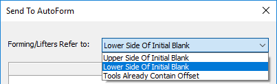
Note: This dropdown option is dimmed when the Kinematics checkbox is marked ON.
Usually, before sending to AutoForm, the tool preparation requires editing the geometry after offsetting the forming shapes and lifters. Therefore, the upper and lower shapes will usually be different, besides the offset. In these cases, use the Tools Already Contain Offset option.
In cases where only the offset is required for all forming shapes and lifters, and no additional geometry editing is required, use either the Upper or Lower Side of Initial Blank options. In these cases, Cimatron automatically duplicates and attaches the geometry to the appropriate opposite side - see below. This duplicated geometry will later be offset in AutoForm according to the material thickness.
|
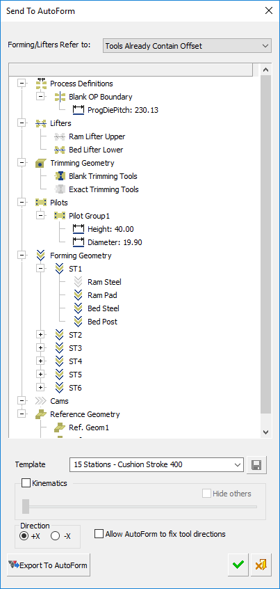
Tools Already Contain Offset |
The selected geometries already contain the required offset (thickness). This is the most common case. See the dropdown example dialogs and the dropdown notes below. |
|
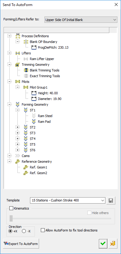
Upper Side of Initial Blank |
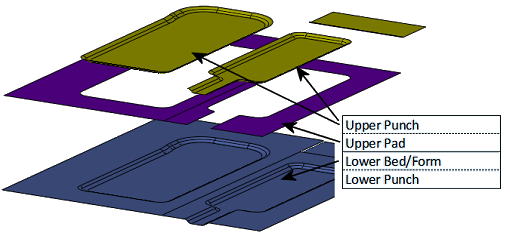
When this option is selected: All Forming Shapes (under the Forming Geometry tree) contain only the 2 upper rows, the Ram Steel and the Ram Pad. Only the Upper Lifter, the Ram Lifter Upper is shown (under the Lifters tree). When selecting faces to attach to the upper Ram Steel and Ram Pad, the geometry is duplicated to the lower (hidden) Bed Steel and Bed Post respectively, when exporting to AutoForm. Similarly, the upper lifter is duplicated to the lower lifter. In AutoForm, select the same option; AutoForm automatically offsets the lower geometry according to the material thickness. See the dropdown example dialogs and the dropdown notes below. |
|
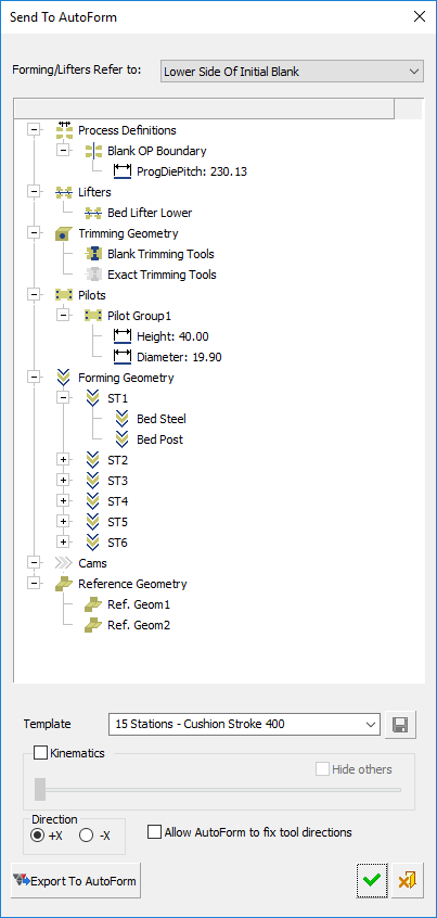
Lower Side of Initial Blank |
When this option is selected: All Forming Shapes (under the Forming Geometry tree) contain only the 2 lower rows, the Bed Steel and the Bed Post. Only the Lower Lifter, the Bed Lifter Lower is shown (under the Lifters tree). When selecting faces to attach to the lower Bed Steel and Bed Post, the geometry is duplicated to the upper (hidden) Ram Steel and Ram Pad respectively, when exporting to AutoForm. Similarly, the lower lifter is duplicated to the upper lifter. In AutoForm, select the same option; AutoForm automatically offsets the upper geometry according to the material thickness. See the dropdown example dialogs and the dropdown notes below. |
Dropdown List - Example Dialogs
|
Upper Side of Initial Blank |
Lower Side of Initial Blank |
Tools Already Contain Offset |
|
|
|
|
-
When changing between the dropdown options, the data relevant to the selected option is displayed in the dialog. Pre-assigned data that is not relevant to the selected option, is hidden; it is not deleted.
For example, if data is already assigned to Bed Steel and the Upper Side of Initial Blank dropdown option is selected, the Bed Steel is hidden and re-displayed if one of the other dropdown options is selected. -
When the Export to AutoForm button is pressed, the hidden data is also exported for each station. However, the IGES file for the hidden data is identical to that of the displayed data.
For example, if the Upper Side of Initial Blank dropdown option is selected, the Bed Steel, Bed Post and the Bed Lifter Lower are also exported for each station. However, the IGES file for the Bed Steel, Bed Post and the Bed Lifter Lower, is a duplicate of that for the Ram Steel, Ram Pad and Ram Lifter Upper, respectively.
Groups of Sets in a tree structure
The groups of sets in the tree represent geometry that will be used in the AutoForm simulation and analysis. Geometry needs to be attached to the relevant sets. Right-click popup options are available for each branch and twig, depending on the context.
An icon of a set is dimmed if there is no geometry attached to the set.
The following branches appear in the dialog:
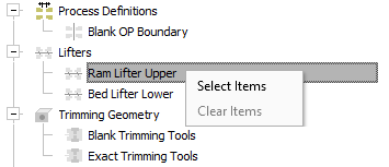
Double-click the set to which geometry is to be attached (or right-click and choose Select Items from the popup menu). This activates the set.
|
Activate the set. |
The set is activated; the cursor focus is now in the graphics window for geometry selection. |
|
|
|
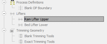
Select the required geometry and <exit><exit> to attach the geometry to the activated set.
|
The relevant geometry is selected. |
Geometry is attached to the set. Note that the set icon is no longer dimmed. |
|
|
|
Process Definitions
To define the Blank OP Boundary:
The Blank Operation Boundary (at the top of the set tree) defines the border between two stations on the strip (the separation area), such as the example below:
![]()
This boundary is initially a sketch wire created in Cimatron. When defining the boundary, the selected wire represents the exact width of the strip in AutoForm.
![]()
When the wire is selected, the parameter ProgDiePitch is automatically updated according to the progression defined in the Setup dialog (determined by the distance between the blank’s Work CS’s); for example:
|
ProgDiePitch parameter: |
Parameter value acquired from the Setup dialog: |
|
|
|
The AutoForm Blank is generated from the OP (Operation) boundary and the pitch value. See the examples below:
The system copies the operation boundary by delta of the pitch (progression):
![]()
![]()
The resulted shape is sent to Autoform as the input blank.
![]()
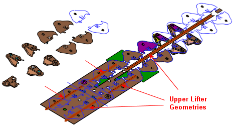
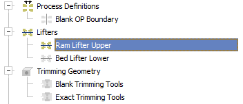
Lifters
Strip lifters are often used to lift the strip slightly when the part requires very little lift to feed it. They also support the strip during pilot entry.
A lifter selection example is shown above (attaching geometry to a set).
Trimming Geometry
This selects the trimming punches that were previously created in the strip part. The Autoselect Trimming Punches popup option automatically selects geometries that were defined as trimming punches. These may also be defined manually.
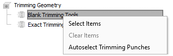
The Exact Trimming Tools refer to exact punch wire geometry such as the inside of holes, etc.
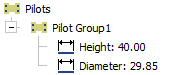
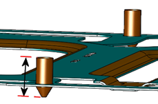
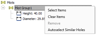
Pilots
When a pilot hole is selected, the system displays the pilot diameter and height. While the diameter is calculated from the selected geometry, the height value is retrieved from the template selected in the Send to AutoForm dialog, see below (for example, 15 Stations - Cushion Stroke 400). The default values that can be changed.
|
Pilot parameter values: |
Pilot height example: |
|
|
|
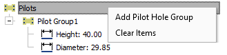
Each pilot group may include multiple holes of the same diameter. The Autoselect Similar Holes popup option automatically selects holes with the same diameter.
|
|
|
Forming Geometry
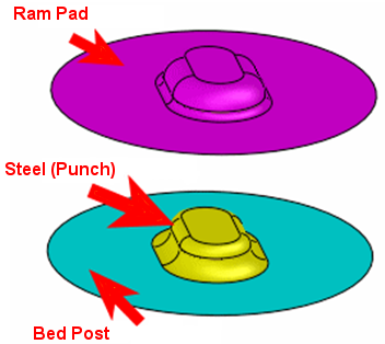
Forming geometry is added to the appropriate groups. As mentioned earlier, it is recommended to color code the forming geometry groups.
For example, in the images below, the yellow faces refer to the upper punch (Steel), purple to the upper (Ram) pad and blue to the lower Bed.
|
|
|
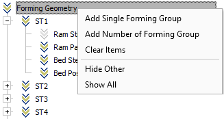
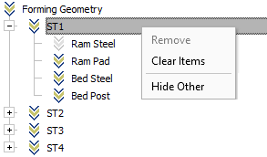
Create forming groups for each station by selecting the appropriate option from the popup menu.
|
|
|
|
Add Single Forming Group |
Add one forming group. |
|
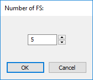
Add Number of Forming Group |
Add multiple forming groups. The following dialog is displayed to set a specific number of groups to be added.
Default: 5 |
|
Clear Items |
Clear assigned data items for all forming shapes. |
|
Hide Other |
Hide everything except for the selected/highlighted geometry. When exiting the dialog, the data (displayed before) is restored. |
|
Show All |
Show all geometry. |
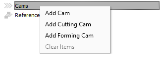
Cams
The Cams branch refers to components that will be moved horizontally.
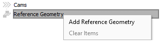
Reference Geometry
Define the reference geometry that will be used later in the Autoform environment. The reference geometry will be used to compare between the predicted result and the required one.
Parameters
The following information appears in the dialog:
|
Template |
Select a template from the dropdown list. This template is included (as Template_ProgSim_ToolsPerStation.afp) in the zip file exported to AutoForm. |
||||||
|
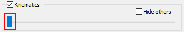
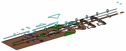
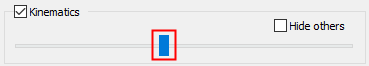
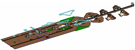
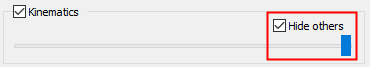
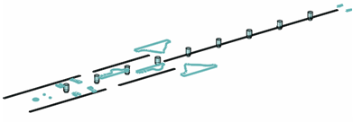
Kinematics |
This is a visual tool to assist in preparing the data for AutoForm and making sure that all required objects are indeed selected and defined correctly. When this checkbox is ON, the trimming punch boundaries are highlighted. Use the slide bar to simulate the opening and closing of the die.
Check the Hide Others option to clearly examine the trimming punches kinematic movement. Hide everything except for the selected/highlighted geometry.
|
||||||
|
Direction |
Define the strip direction +X or -X. |
||||||
|
Allow AutoForm to fix tool directions |
When this checkbox is ON, enable AutoForm to automatically fix tool directions. |
Dialog Buttons
The following buttons are in the dialog
|
Export to AutoForm |
Export the data to AutoForm. The defined data is exported into a zip file containing templates (xml
files) and IGES files to run within AutoForm.
In AutoForm, the following operations are performed:
|
|
Save: Save the settings. |
|
|
OK: Accept the changes, perform the operation, and close the current dialog/task. The zip file exported from
Cimatron
using the Send
To AutoForm function, is loaded into AutoForm for
simulation and analysis.
|
|
|
Cancel: Cancel all changes and close the dialog/task without saving the settings. |
|