|
|
Automatic Conformal Cooling Curve  : Options and Results
![]()
![]()

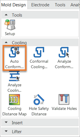
Access: Open this function from one of the following locations:
-
Select Mold Design > Cooling > Automatic Conformal Cooling Curve from the menu bar.
-
Select Cooling > Automatic Conformal Cooling from the Mold Design Guide Toolbar.
Automatically create conformal cooling curves by analyzing the part's geometry.
|
|
|
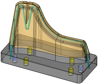
Part on which the function is to be performed |
Required Step 1 
-
Pick the active faces that need to be cooled. The following parameters are displayed:

Faces /
A toggle option to select the required faces. Pick face(s) from a single B-rep body.
Facets
A toggle option to select the required facets (triangles). Pick facet(s) from a single mesh object.
See Facet Selection for a description of the various facet selection options.
Expand to Same Color Faces / Do not Expand
This is a toggle option that enables the selection of faces to be expanded to those of the same color as the first selected face.
In this mode, when a single face is selected, the selection is expanded to adjacent faces of the same color as the selected face.
In this mode, when a single face is selected, the selection is not expanded to the adjacent faces.
Required Step 2 
-
Set the cooling parameters and pick the In/Out points if required. The following parameters are displayed:

Set the parameters
Pick two points for the cooling circuit which will be labeled as In and Out; these are the in and out points respectively for the cooling circuit.
A direction arrow is displayed defining the printing direction. The default direction is the Z direction of the active UCS.
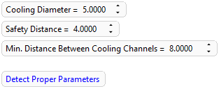
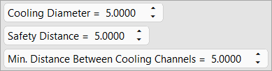
Screen Parameter Options
Preset the required diameter of the cooling channels that are to be created using the Conformal Cooling Design function. The last used settings are kept and are used for subsequent operations.
Default = 5 mm (0.2 inch)
Minimum = 0.1 mm
Maximum = 100 mmPreset the required safety distance from walls. The last used settings are kept and are used for subsequent operations.
Default = 5 mm (0.2 inch)
Minimum = 0.1 mm
Maximum = 100 mmPreset the minimum required distance from other cooling channels. The last used settings are kept and are used for subsequent operations.
Default = 5 mm (0.2 inch)
Minimum = 0.1 mm
Maximum = 100 mmNote: The Min. Distance Between Cooling Channels value should be ≥ the Safety Distance value. If it is less than the Safety Distance, the Min. Distance Between Cooling Channels value is displayed in red.
Detect Proper Parameters
Click this option to enable system-defined parameter settings to achieve the desired result. This option is displayed if the selected cooling faces are detected by the system as walls with almost the same thickness.
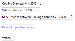
When this option is selected, the system automatically adjusts the parameter values to achieve optimum results and the Vertical/Horizontal option is displayed. The Detect Proper Parameters option is then dimmed and will be enabled again if one of the detected parameters is changed. See the examples below.
Example:Example:Selected cooling faces are detected by the system as walls with almost the same thickness
When the Detect Proper Parameters option is clicked, the system automatically adjusts the parameter values to achieve optimum results
Vertical/Horizontal
This is a toggle option to create the conformal cooling circuit either Vertically or Horizontally. This option is displayed if the selected cooling faces are detected by the system as walls with almost the same thickness and after the Detect Proper Parameters option is clicked.
Example:Example: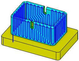

Automatic conformal cooling circuit created vertically
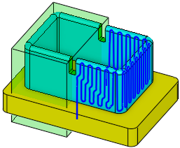
Automatic conformal cooling circuit created horizontally
Optional Step 1 
- Pick additional closed object(s), such as cooling channels (even if they were not yet cut with the part), to make sure that the created cooling curve circuit stays further away from them.
|
|
|
|
|
Closed object selected |

Optional Step 2 
-
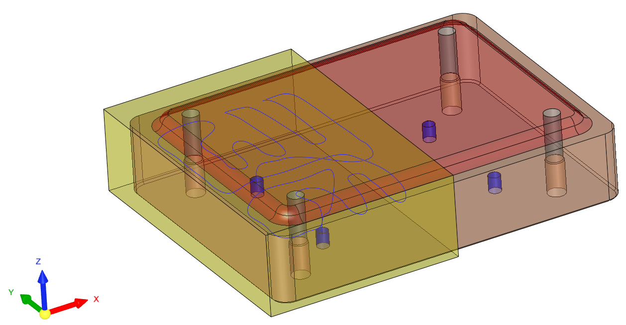
Pick a closed object that defines a virtual volume used to split the cooling circuit into several circuits. The circuit may be created either inside or outside the virtual volume.
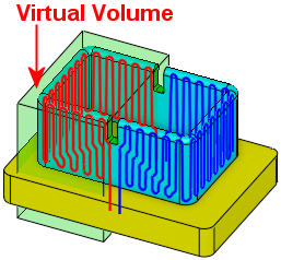
Virtual volume used to create several circuits
Screen Parameter Options
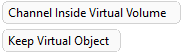
Channel Inside Virtual Volume / Channel Outside Virtual Volume
This is a toggle option to create a circuit either inside or outside the virtual volume of the selected object.
Example:Example: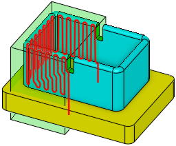
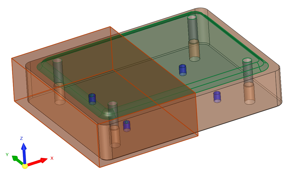
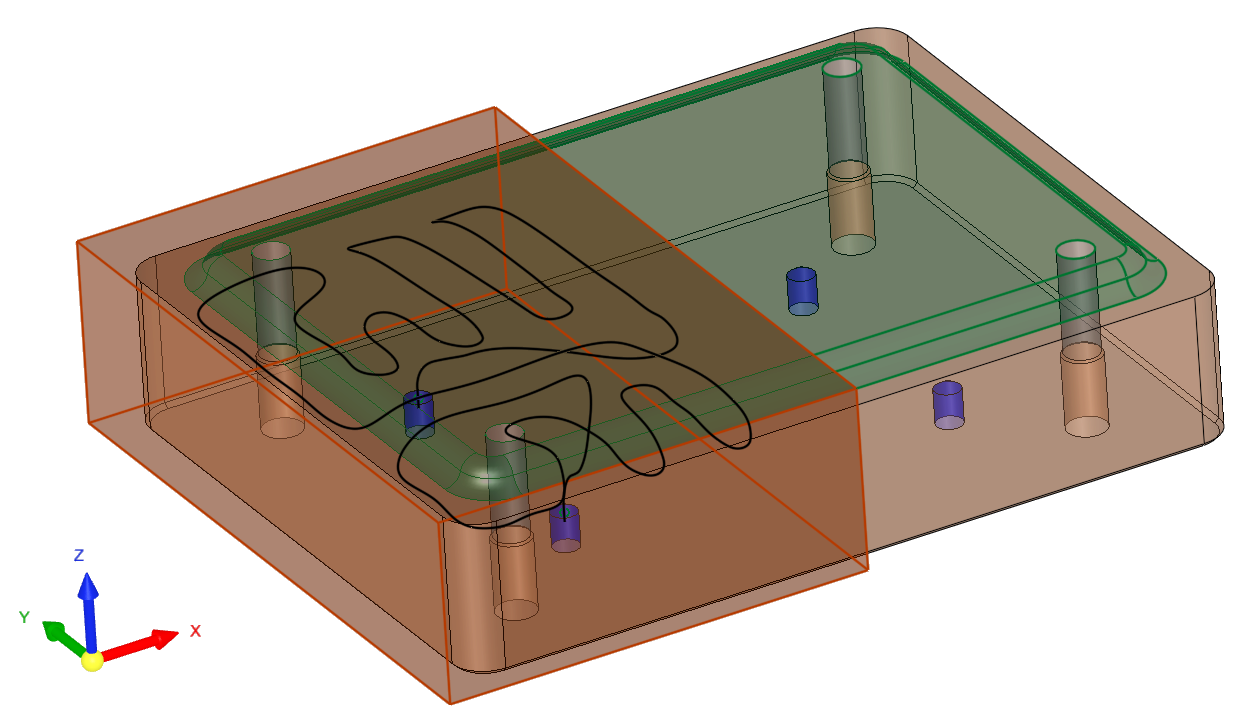
Circuit Inside Virtual Volume
Circuit Outside Virtual Volume
Create a circuit inside the virtual volume of the selected object.
Create a circuit outside the virtual volume of the selected object.
Keep Virtual Object / Remove Virtual Object
This is a toggle option that enables the virtual object to be kept or removed from the operation.
Example:Example: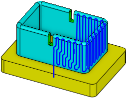
Keep Virtual Volume
Remove Virtual Volume
If the virtual object is not in the active part, this parameter is displayed as Keep Virtual Object and dimmed.
Keep the selected virtual object.
This is the default option.Do not keep the selected virtual object.
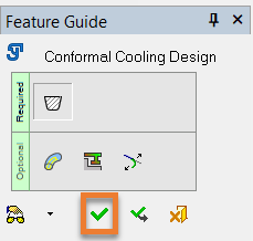
- Click OKOK
 or ApplyApply
 in the Feature Guide to complete the function. The system will then calculate the optimal path of the conformal cooling channel and create a curve to be used as an input for the Conformal Cooling Design function as shown below.
|
|
|
|
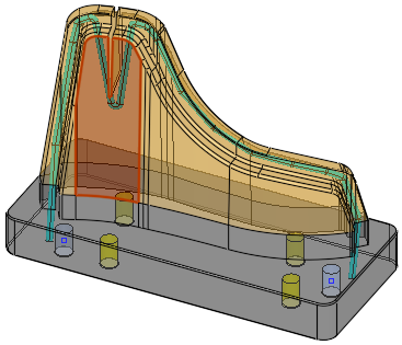
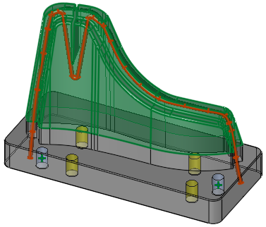
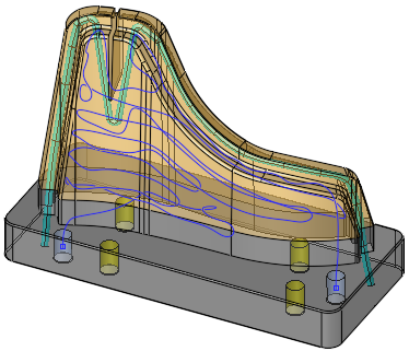
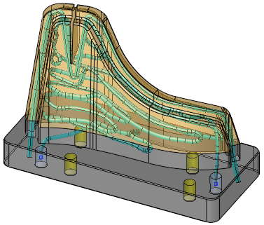
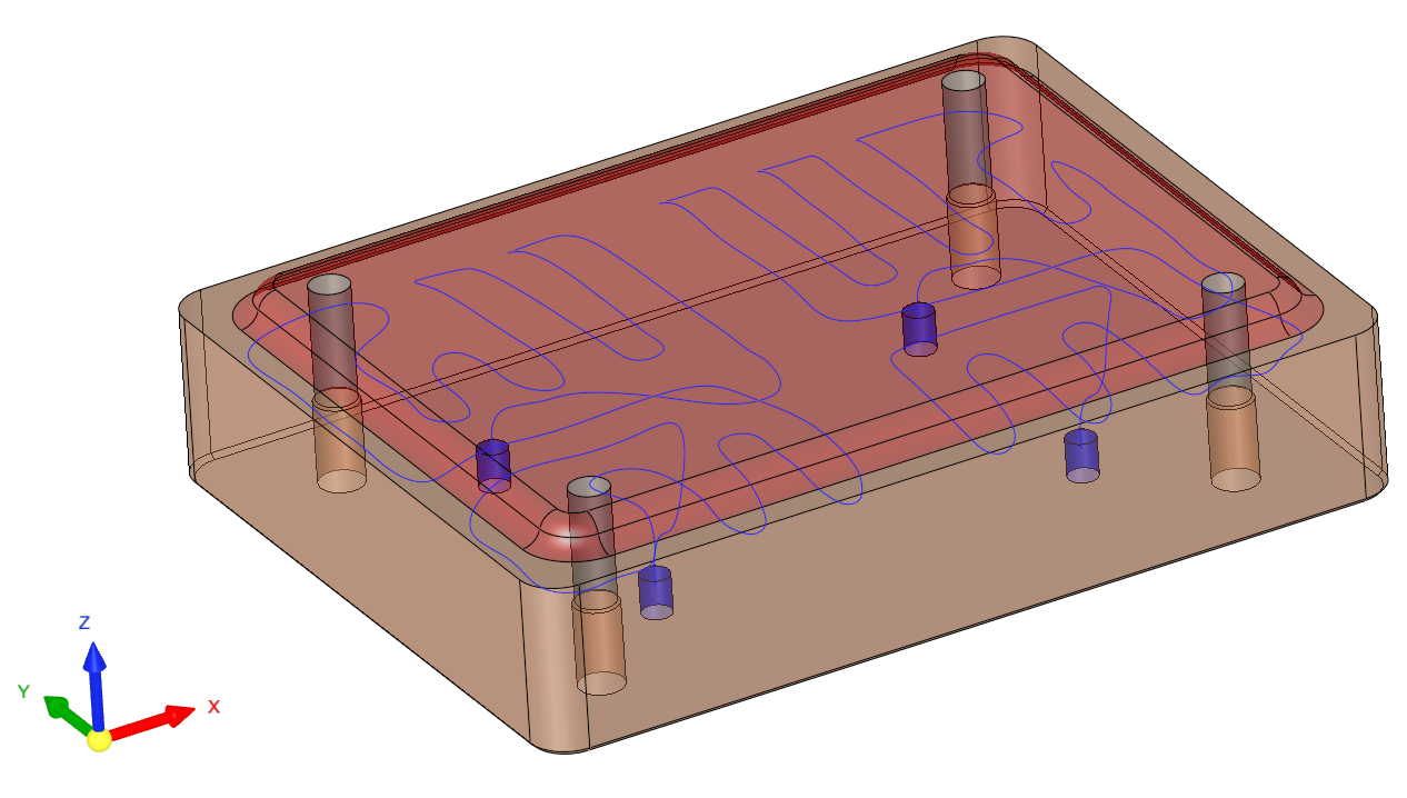
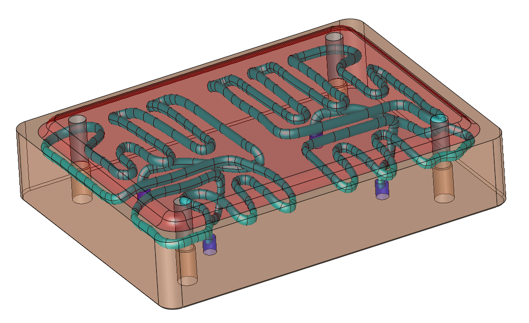
The optimal path of the conformal cooling channel created by the Automatic Conformal Cooling Curve function. This curve is used as input for the Conformal Cooling Design function |
The cooling channel created by the Conformal Cooling Design function based on the input - the optimal cooling path curve created by the Automatic Conformal Cooling Curve function |
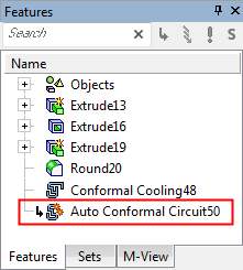
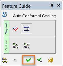
When completed, the Auto Conformal Cooling Circuit feature will appear in the Feature Tree as follows:
Detailed Interaction
- Creating Conformal Cooling Channels with the Automated Conformal Cooling Curve FunctionCreating Conformal Cooling Channels with the Automated Conformal Cooling Curve Function
-
Open a Mold file.
-
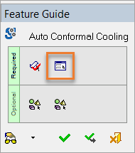
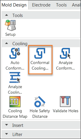
Navigate to Mold Design in the menu bar and click the Automated Conformal Cooling Curve icon.
Note: You can also select this function from the Mold Design Guide Toolbar. Click on the Access button at the top of this page for more information.

-
The screen parameter, Expand to Same Color Faces, appears in the graphics pane. Click this screen parameter to toggle between the following options:
-
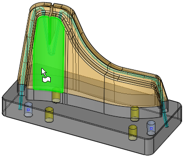
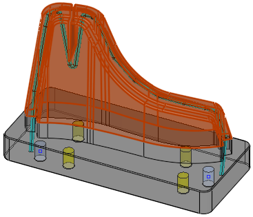
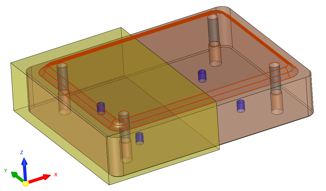
For this exercise, click the Expand to Same Color Faces option and pick a face (in this example, a single purple face is selected, which selects all purple faces).


Note: When clicking on a single face, all faces with the same color were also highlighted (shown below in orange). This is the result of selecting the Expand to Same Color Faces option.

-
ExitExit.
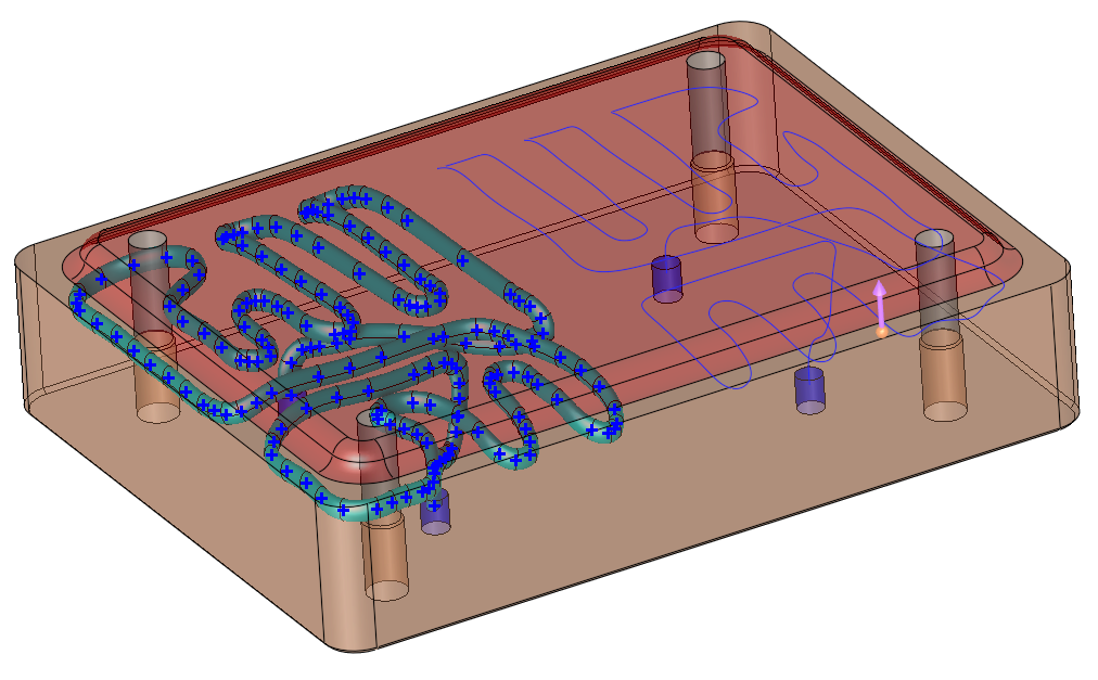
The following screen parameters are displayed: -
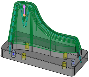
Set a value for each screen parameter as needed.
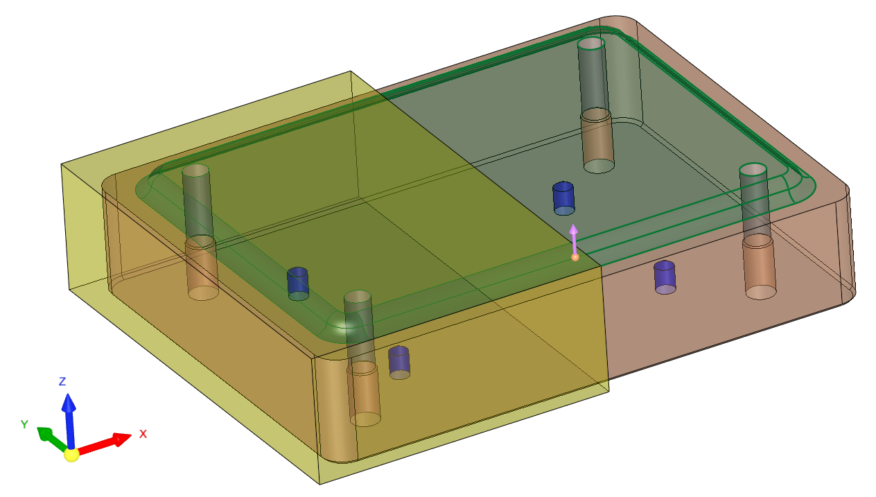
Also, notice the purple arrow that indicates the printing orientation (towards the top layer of printing). This arrow also indicates the direction of the coolant in and out and can be flipped or set to any direction.

-
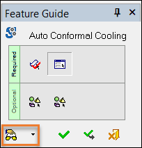
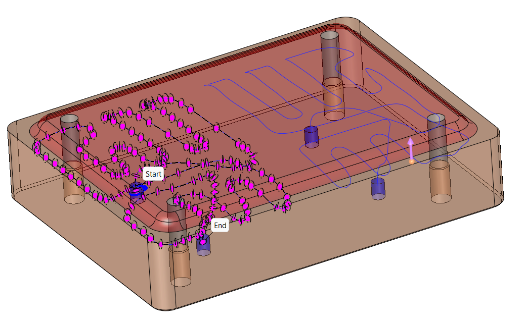
After setting the screen parameter values, click the Preview button in the Auto Conformal Cooling Feature Guide.

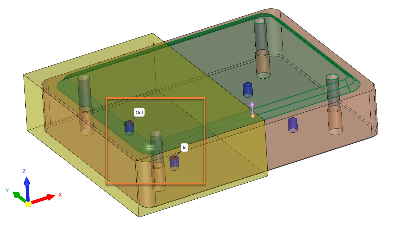
A preview of the curve is displayed in the graphics pane. Note that the In and Out ends are not yet set. These will be set in the following step.

-
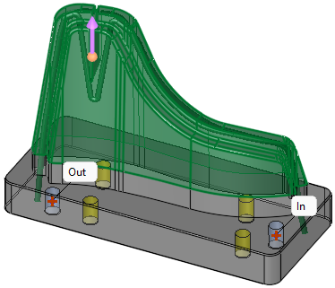
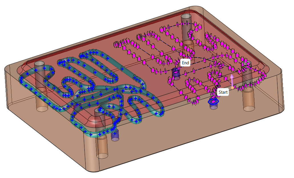
Click the center of the holes for the In and Out ends. The first hole picked will indicate where the curve will go In, and the next hole picked will indicate where the curve will go Out.

-
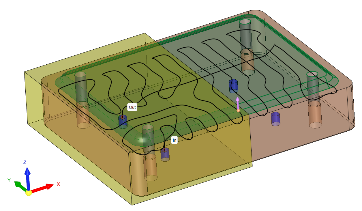
Click the Preview button again in the Auto Conformal Cooling Feature Guide to see the repositioned In and Out ends.

-
Click the OK button in the Auto Conformal Cooling Feature Guide to create the curve for the cooling channel.


The following steps will show how to use the Conformal Cooling Design function to create conformal cooling channels for the curve.
-
Navigate to Mold Design in the menu bar and click the Conformal Cooling Design icon.

-
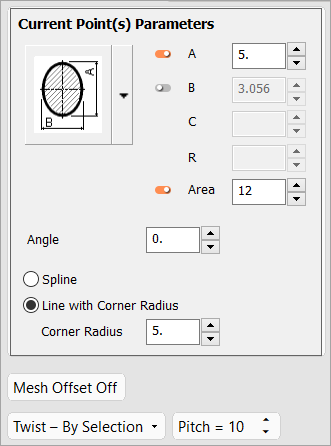
The Current Point(s) Parameters dialog appears. Set the parameters as indicated below and click anywhere on the curve.


-
Click the OK button in the Conformal Cooling Design Feature Guide to create the cooling channels.


-
-
Creating Split Cooling ChannelsCreating Split Cooling Channels
-
Open a Mold file.
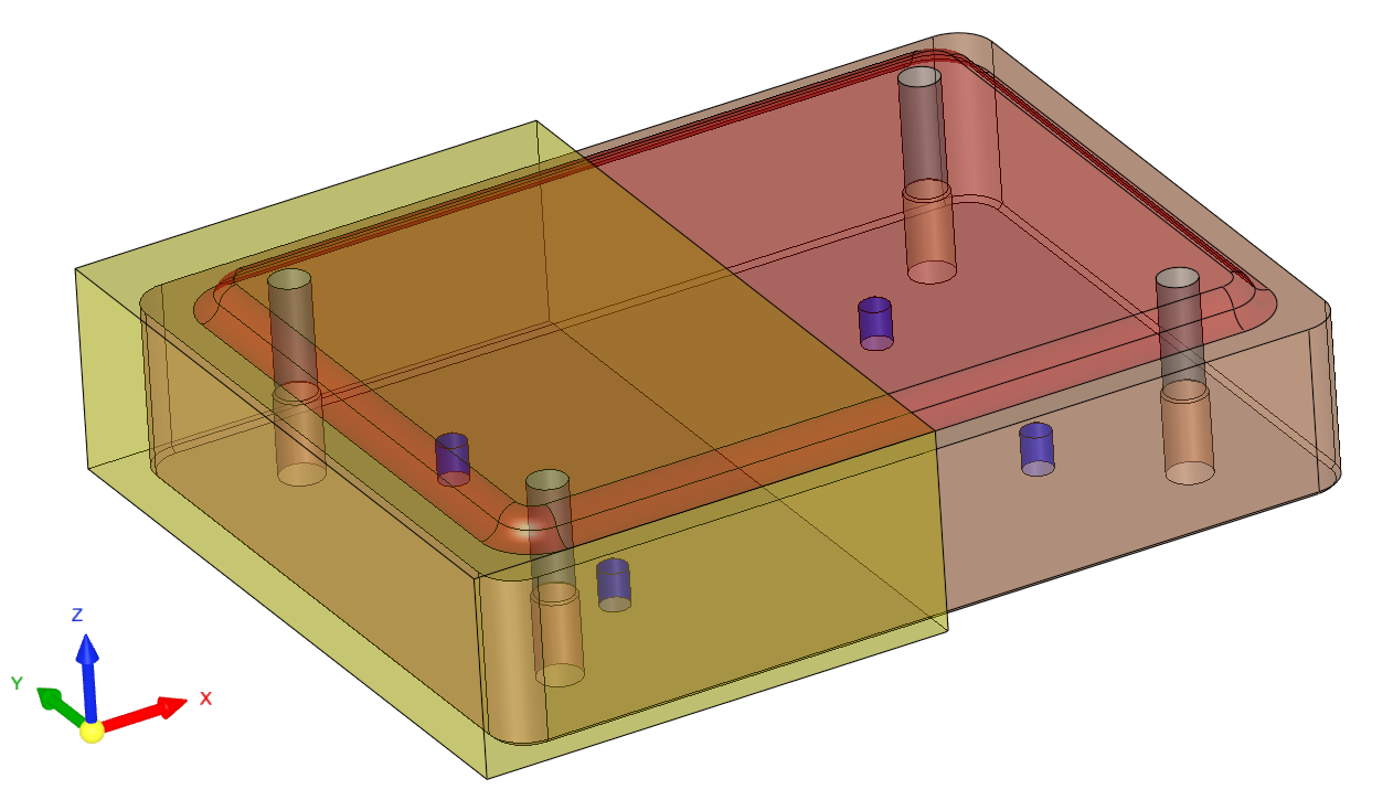
There are two objects in this file. The yellow object will be selected as the Virtual Object later in this exercise. -
Click Mold Design > Automated Conformal Cooling Curve.
-
The screen parameter, Expand to Same Color Faces, is displayed in the graphics pane. Click this screen parameter to toggle between the following options:
For this exercise, pick the Expand to Same Color Faces option and pick a face (in this example, a single red face is selected, which selects all red faces).

-
ExitExit. This automatically opens the Required Step 2 (Define Cooling Parameters) in the Auto Conformal Cooling Feature Guide.
-
The following screen parameters are displayed:
Set a value for each screen parameter as needed. For this exercise, set the parameters as shown below.
-
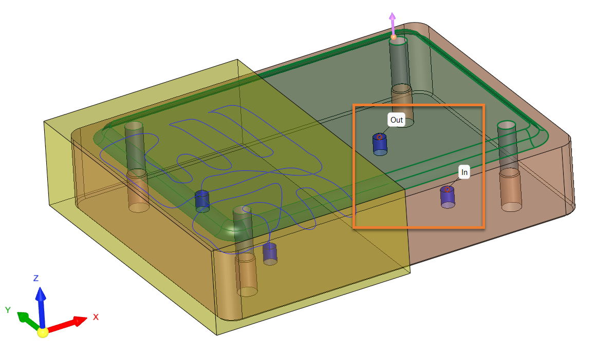
Click two center points for the In and Out ends of the curve, selecting the In center point first and then the Out.
-
Click the Preview button in the Auto Conformal Cooling Feature Guide to see a preview of the curve.
A single cooling curve runs through the entire region. The following steps will show how to restrict the cooling curve to a particular region by using the Pick Virtual Object optional step.
-
From the Auto Conformal Cooling Feature Guide, select the Pick Virtual Object icon.
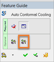
-
Click the yellow object to select this region to run the cooling curve.
The following screen parameters are displayed. Pick a parameter to toggle between the following options:
Set the parameters to Channel Inside Virtual Volume and Keep Virtual Object.
-
Click the Preview button in the Auto Conformal Cooling Feature Guide. A preview of the curve is displayed within the region of the Virtual Object previously selected.
-
Click OK in the Auto Conformal Cooling Feature Guide to create the curve in the selected region.
The following steps will show how to create a second separate cooling curve in a different region of the mold.
-
Navigate to Mold Design in the menu bar and pickpick the Auto Conformal Cooling Curve icon.
-
Click a red face.
-
Exit.
-
Click two center points for the In and Out ends of the curve, selecting the In center point first and then the Out.
-
Click the Preview button in the Auto Conformal Cooling Feature Guide to see a preview of the curve.
-
From the Auto Conformal Cooling Feature Guide, select the Pick Virtual Object icon.
-
Click the Virtual Object (yellow object).
-
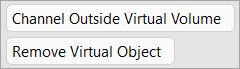
Navigate to the screen parameters and pick Channel Outside Virtual Volume and Remove Virtual Object. Click the Preview button in the Feature Guide to display the curve.
-
Click OK in the Auto Conformal Cooling Feature Guide to create the curve for that region.
The following steps will create two separate (split) cooling channels using the Conformal Cooling Design function.
-
Navigate to Mold Design in the menu bar and click the Conformal Cooling Design icon.
-
The Current Point(s) Parameters dialog appears. Set the parameters as needed and clcik anywhere on the first curve.
-
Click ApplyApply
 in the Conformal Cooling Design Feature Guide to create the cooling channels.
-
Click the second curve.
-
Click OK in the Conformal Cooling Design Feature Guide.
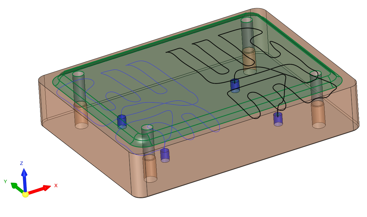
Two separate conformal cooling channels have been created.
-

|