Drive (Solid) : Options and Results


Access: Open this function from the following location:
-
Select Solid > Creation > Drive from the menu bar.
Drive a contour to add or remove material.
This function allows you to create a new solid object, add to an existing solid object, or remove material from a solid object by driving a 2D sketch along a spine.
There are three primary options for Drive:
|
|
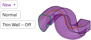
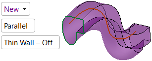
Create a new solid object by driving the selected entities. New extrusions are considered independent objects. |
|
|
|
Add to an existing solid object by driving the selected entities. Added extrusions are added to the active object. |
|
|
|
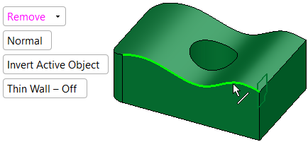
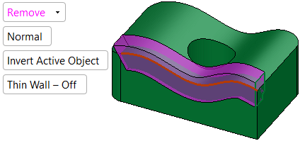
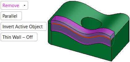
Remove material from a solid object by driving the selected entities. Material is removed only from the active object. |
IMPORTANT
-
Objects created by New will be considered independent objects.
-
Those created by Add will be added to the active object.
-
For Remove operations, material will be removed only from the current active object.
Notes:
-
If only one object exists in the file it is automatically active, unless manually deactivated or if the active object is deleted. See Activate / Deactivate and Activating Objects.
-
For Add and Remove operations you can use wires or faces from a non-activated component (external reference).
Required Step 1 
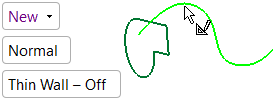
Select a closed 2D composite curve or sketch.
Drive > New / Add |
Drive > Remove |
|
|
|
Notes:
-
If you enter Drive immediately after creating a closed 2D composite curve or sketch, the entity is automatically included in Step 1.
-
If you select a sketch that contains more than one closed curve sequence, all closed curve sequences will be driven. In order for a sketch to be selected, however, it must contain only closed curve sequences.
Required Step 2 
Select a composite curve and set drive parameters. The spine must be one curve (line, spline, edge, etc). If needed you can join several curves / edges into one by using the Composite Curve function.
Drive > New / Add |
Drive > Remove |
|
|
|
Parameters
|
New / |
New – Create a new solid object by driving the selected entities. New extrusions are considered independent objects. Add – Add to an existing solid object by driving the selected entities. Added extrusions are added to the active object. Remove – Remove material from a solid object by driving the selected entities. Material is removed only from the active object. The default displayed option is determined as follows: New if there is no object. Add if there is an object and the last used option was New or Add. Remove if there is an object and the last used option was Remove. |
||||||||||||||||||||
|
Corner Radius |
This parameter is only available when the Round Corners toggle option is selected. |
||||||||||||||||||||
|
Invert Active Object |
This parameter is only available when the Add or Remove toggle option is selected (see above). |
||||||||||||||||||||
|
Normal / |
This is toggle option that enables you to define the orientation of the sections with the spine.
|
||||||||||||||||||||
|
Thin Wall - Off / |
This toggle option enables you to create a thin-walled solid.
The Thin Wall toggle option appears in the following functions: For additional information, see Thin Wall. |
||||||||||||||||||||
|
Middle Plane / |
These parameters are only available when the Thin Wall - On toggle parameter is selected. |
||||||||||||||||||||
|
Sharp Corners / |
These parameters are only available when the Thin Wall - On toggle parameter is selected. |
||||||||||||||||||||
|
Thickness |
This parameter is only available when the Thin Wall - On toggle parameter is selected. |
Optional Step 1 
-
Pick a constraint plane to constrain the section if required.
-
A screen parameter appears with the following available options. Select an option.
|
Active XY |
Maintain the section to the Active XY. This is the default option. |
|
None |
The section is not maintained to any plane. |
|
Plane |
Maintain the section normal to the plane. |
|
Z Referenced |
Maintain the section normal to the spine as it follows a 3D curve. Rotation stays oriented to active Z direction consistent with the original selected section. |
|
In the picture below, the profile (section) is the RED wire and the path is BLUE. |
The result without picking a constraint plane. |
The result after picking a constraint plane (for example the Active XY). |
|
|
|
|
Another look at this example from the top view.
|
Without picking a constraint plane |
After picking a constraint plane (for example the Active XY) |
|
|
|
This means that without picking a constraint plane, the section could be rotated (twisted) along the local axis in any point normal to the path, while after picking a constraint plane it is constrained in XY (the rotation (of the section) is possible in the Z direction only).
Note: In order to use this step, the spine selected in Required Step 2 must be smooth.
Optional Step 2 
If you want to add a draft angle to the drive, see Defining a Draft Angle.
This option is not available in the following cases:
-
If a closed spine (which could be a wire or a curve) is selected in Required Step 2.
-
If the Parallel option is used in Required Step 2.
-
If a constraint plane (using the option Plane) is used in Optional Step 1.
Screen parameters
|
Draft Angle / |
Draft Angle – Define a draft angle for this drive. None – No draft angle is defined and the options/parameters for this step are not displayed. |
|
Flip ---> / |
Flip the draft angle's direction. |
|
Draft Angle = |
Enter a draft angle value. Valid entries are between 0 and 89 degrees. |
Optional Step 3 
-
Change the active object. This option is only available in the following cases:
-
For Add and Remove operations when creating a feature. The option is not available when editing a created feature.
-
If there is more than one (1) object in the active part.
-
A screen parameter appears with the following available options; select one.
|
Keep Original Active Object |
Keep the active object originally used in the function. |
|
Activate Selected Object |
Change the active object to the selected object. Pick an object as required. |
-
When you have completed the steps, click OK
 or Apply
  in the Feature Guide to complete the function.
When completed, the Solid Drive feature will appear in the Feature Tree.
|
Drive > New |
Drive > Add |
Drive > Remove |
|
|
|
|