|
|
Extend Planar & Cones  : Options and Results
Access: Open this function from one of the following locations:
-
Click the
 button in the toolbar.
 -
Select Faces > Create Faces > Extend Planar & Cones from the menu bar.
-
Select Parting Surfaces > Extend Planar & Cones from the Mold Design Guide Toolbar or Parting Guide Toolbar.
Extend stitched adjacent simple faces to reach a reference geometry (closed sketch, closed 2D composite or planar face).
This function enables you to extend adjacent planar, cylindrical or conic faces (belonging to the same object) or NURBs that can be simplified to these types) for creating Binder Faces.
Required Step 1 
Pick adjacent planar, cone or cylindrical faces.
Note: The selected faces MUST be adjacent and belong to the same object (meaning, you cannot select faces from different objects).
|
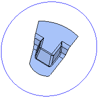
Original faces: |
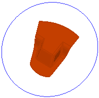
Faces selected: |
|
|
|
Required Step 2 
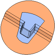
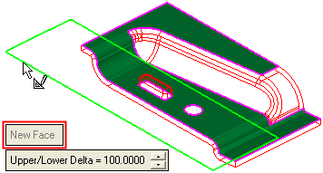
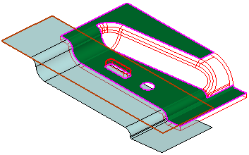
Pick a reference entity to which the selected faces will be extended and set the parameters. This reference entity can be a reference closed sketch, closed 2D composite or planar face. In the example below, a closed sketch is selected.
The following parameters/options are displayed:
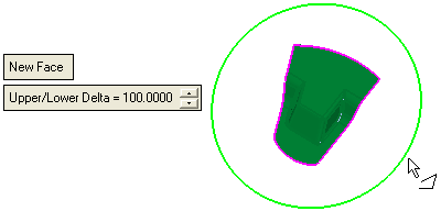
|
New Face |
This is a toggle option: New Face / Same Face.
Note: When creating parting surfaces in the Assembly environment, if the faces selected in step 1 belong to an external (non-active part), the following occurs when switching to step 2:
|
||||||||||||||
|
Upper/Lower Delta |
This parameter controls the extension value of faces that are vertical (or almost vertical) to the picked wire/sketch plane. It controls the cupping plane/face of the upper and lower bounding box of the selected faces. When the result is created, the faces will be extended towards an imaginary sweep face created by this sketch. It is created, as follows:
Note: This parameter is mainly used to control the extension value of faces that are vertical (or almost vertical) to the picked wire/sketch plane. |
Optional Step 1 
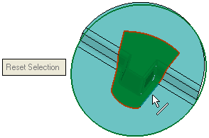
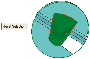
Unselect the required closed edges that you do not want to include in the extend operation. For example:
|
Pick the required edge(s). |
If required, select Reset Selection to clear the selection. This option is grayed out until the first edge is picked. |
|
|
|
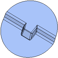
Result:
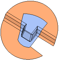
Click OKOK or ApplyApply in the Feature Guide to complete the function.
When completed, the Extend Planar & Cones feature will appear in the Feature Tree as follows:

|


