|
|
Add Forming Shape  : Options and Results
Access: Open this function from one of the following locations:
-
Select Die Design > Forming Shapes > Add Forming from the menu bar.
-
Select Forming Shapes > Add Forming from the following Die Design Guide: Die Process Design Guide (Forming).
Add a forming shape (where the part is gradually unfolded) to the forming environment. This is usually imported from an existing forming shape, however, an external part may also be added.
These forming shapes are generally copies of the master Die Design file, and are changed using the bend, unfold, unbend operations.
The procedure below describes how to select a part and add it as a new forming shape. The example below shows how to add a new forming part by selecting it.
Alternatively, you can add a new forming shape using one of the following options:
-
Open File
 : Select this option to open another *. elt file.
 -
Import File:
 : Select this option to import a file directly from the Data Interface ( DI).
 -
Add New
 : Select this checkbox to add a new blank part and create sketches.
Required Step 1 
Pick the Forming Part.
This example below shows how to select and add a new forming part.
-
Select the required forming part to add. The selected part is highlighted in red, as shown below:

-
In the Add Forming Part window, click OK
 . The selected part is added and highlighted in grey,

Required Step 2 
Place the Forming Part.
This step describes how to place the part using the navigation buttons,
-
Click the right navigational button (highlighted in red). The part has been relocated one step to the right,

-
Click the top navigational button (highlighted in red). The part has been relocated to the top far right,

Notes:
-
When using the top
 and bottom
  navigational arrows, the system always relocates the part at the end of the row. You can use these top
  , bottom
  , left
  and right
  navigational buttons to locate the part, as required.
 -
When one forming shape row exists, if you add a forming shape, the system only enables you to move a forming shape left or right (only the left
 or right
  arrows are enabled),

After adding a second forming shape row, the up and down arrows also become enabled,

-
-
Click
 . The following dropdown list is displayed:
-
Select the required option,
-
Copy Part: Saves the part under a different name (like, Save As), maintaining all features.
-
Copy Part Import: Imports the part from another *. elt file without its features and is incorporated into the current part.
-
-
When
 is selected,
  is enabled. Click this button to display the following options:
-
Regular: Places the part as is in the current *. elt file.
-
Mirror XY: Places the part according to user defined Form CS ( XY) in the current *. elt file.
-
Mirror XZ:Places the part according to user defined Form CS ( XZ) in the current *. elt file.
-
Mirror ZX:Places the part according to user defined Form CS ( ZX)) in the current *. elt file.
-
-
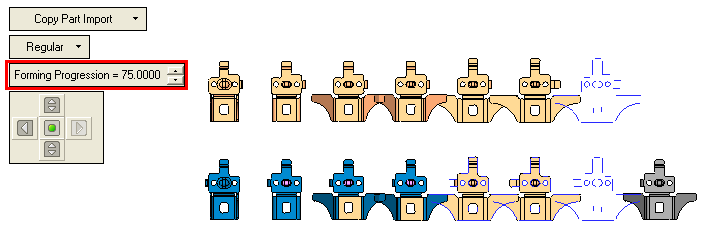
In the Forming Progression field, enter a value to determine the distance between two sequence parts. For example, entering a value of 75. The distance between the parts changes,

-
Click OKOK or ApplyApply in the Feature Guide to complete the function.
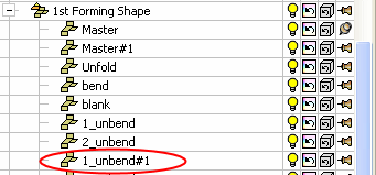
When completed, the new Forming Shape will appear in the Feature Tree

|
