|
|
Dynamic Constraint Lines: Horizontal or Vertical Alignment
Notes:
-
The constraints that appear on the screen depend on which entities are currently in the display area. For example, you will not see parallel constraint to a line that is not in the display.
-
If you want to create alignments with entities that are not in the current sketch, you must add the entities to the sketch as reference entities.
-
You can also add constraints after entities are created. See Adding Constraints.
-
You can control which constraint lines appear by the Constraint Filter.
Dashed Orange Constraint Lines
Horizontal / Vertical
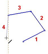
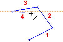
When a new line approaches horizontal or vertical alignment, a dashed orange constraint line is displayed next to the new line.
The following examples show the dashed orange lines indicating line 4 is close to alignment with the X or Y axis.
|
Line 4 will be vertical. |
Line 4 will be horizontal. |
|
|
|
Dashed Purple Constraint Lines
Same X or same Y constraint
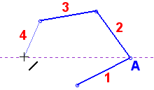
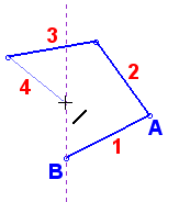
When the end point of a new line and the end point of an existing line are horizontally or vertically aligned (same X or Y coordinate), a dashed purple line appears connecting the two points. You can then create a new line connecting the two points.
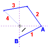
In the following examples, the end point of line 4 is horizontally or vertically aligned with an existing line's end point coordinate (point A or point B).
|
The endpoint of line 4 will be horizontal from point A. |
The endpoint of line 4 will be vertical from point B. |
The endpoint of line 4 will be horizontal from point A and vertical from point B. |
|
|
|
|
Note: When you use Dynamic Constraint Lines to help you position a new entity, the new entity will be constrained to either the existing entity or the XY axis. When the new entity is positioned relative to an existing entity, a mutual constraint relationship is created with the existing entity. If required, you can subsequently break an entity's constraints to make it independent of all other entities and the XY axis.
|
