|
|
Add Reference 

Access: Invoke the Sketcher, define the sketch plane and then invoke this function from one of the following locations:
-
Click the Add Reference button
in the Sketcher
toolbar. -
Right-click the graphics area and select Add Reference from the popup menu.
Add selected entities as reference entities in the sketch.
Project entities located on another plane or another sketch onto the current sketching plane as reference entities. Various operations can be performed using the reference entities, for example, using them in the constraining and dimensioning functions - see below.
Notes:
-
Reference entities are not included as geometry in the sketch, and they will disappear when you exit the sketch. (If you re-enter the sketch, reference entities will reappear.) If you want to add geometry from another plane or sketch onto the current sketch, see Adding Geometry.
-
Reference Points - To distinguish between regular points and reference points in the Sketcher, reference points (added using Add Reference or points turned into construction points) are diamond shaped and are colored differently.
Example:Example:
Create reference geometry on the Sketcher plane
-
Select a plane. The selected plane is highlighted.
-
InvokeInvoke the Add Reference tool.
-
Pick geometry. The following parameters are displayed:
Any Geometry
This is a toggle option Any Geometry / Cylindrical Faces Only that enables you to choose the type of geometry to pick.
When selecting faces, make sure that the Face option is selected in the Selection Filter before picking the face.
Project
This is a toggle option Project / Intersect that enables you to either project onto or intersect with the selected sketch plane.
- There are two options: Project and Intersect.
-
If the Project option is selected, the selected geometry is projected onto the sketch plane as a construction (reference) geometry. The construction geometry can be used to assist you in placing and dimensioning entities in the current plane.
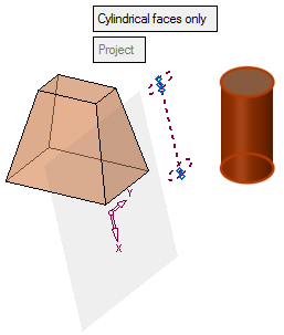
ExampleExampleCylindrical Faces Only Projection Example:
In the example below, a cylindrical face is selected. Note that entities that are not normal to the sketch plane can be selected (as seen below).
The result of this operation is that the selected geometry is projected onto the sketch plane as a construction geometry. In this example, since the selected geometry is a cylindrical face, the construction geometry is a line which is a projection of the cylinder axis and is the same length as the cylindrical face.
-
If the Intersect option is selected, the common geometry (between the selected geometry and sketch plane) is highlighted. In the case of an intersection point (of the selected geometry with the sketch plane), the intersection point is highlighted.
ExampleExampleAny Geometry Intersect Example:
The geometry is selected. The intersection point of the geometry with the sketch plane is marked with a reference point. 
-
-
You can use the Undo function to cancel your selection.
-
When finished, press OK
 or Apply
  in the Feature Guide or on the Popup Submenu to complete the function. The Sketcher feature will appear in the Feature Tree.
Operations on Reference Entities
Various operations can be performed using the reference entities, for example, using them in the constraining and dimensioning functions - as shown below.
Reference Entity Constraints
Reference entities can be used when setting constraints with other entities. In the examples below a line is assigned a parallel constraint with a reference entity.
|
A reference entity is selected: |
A line entity is selected: |
A constraint is selected (in this case, a parallel constraint) and the line is constrained to the reference entity. |
|
|
|
|
Reference Entity Dimensioning
Reference entities can be used when dimensioning with other entities, as shown in the examples below:
|
A reference entity is selected: |
A line entity is selected: |
The relevant dimension is displayed (in this case, the angle between the selected entities). |
|
|
|
|
The Automatic Reference option is not selected by default but must be set for working on a specific sketch.
Note: If you add a spline close to an arc or line, the spline is turned into an arc or line if it is within a predefined closeness tolerance level (currently 0.001 mm and 0.00004 inch). If it does not meet the tolerance level, then the spline remains as a spline.
|