|
|
Linear Dimensions 

Access: Open this function from one of the following locations:
-
Click
in the toolbar. -
Select Symbols > Textual > Dimension from the menu bar.
-
Select Dimension on the popup menu (right-click the graphics pane area).
Create Linear dimensions.
|
Linear Dimension dialog Click on an item in the dialog for a description. See below for additional information. |
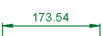
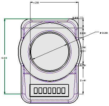
Example Linear dimension |
|
|
|

See Linear Oblique.
See the Advanced Area Options below.
Creating Linear dimensions
InvokeInvoke the Dimensions function. A grayed-out dialog is initially displayed.
See the Dimensioning Process for additional information.
Pick the entity to be dimensioned. The following linear dimensions are available:
Position the dimension.
Edit its parameters with the help of the hot spots and tips either directly in the graphics pane area or on the popup submenu. Change font style ![]() and character size also, if required.
and character size also, if required.
To complete the current operation and remain in the dialog, select Apply ![]() or <exit><exit>.
or <exit><exit>.
To exit the function, select Close ![]() .
.
Notes:
-
For additional information, see the Dimensioning Process and the attached notes.
-
For Linear Dimensions, see Align to Symbol to align the new dimension with an existing one.
-
For Linear and Radial Dimensions:
Dimensions created on edges of faces with a hole attribute or thread/tap attribute will get the data automatically ; this is applicable to linear or radial dimensions. If a hole attribute (of the type Accurate Hole) or a thread/tap attribute is attached to the face being dimensioned, a checkbox is displayed in the Dimension dialog enabling automatic update of the dimension. See Dimension Dialog for Radial Dimensions and specifically the Automatic Accuracy and Automatic Thread/Tap explanations in Radial Dimensions.
Dimension dialog for Linear dimensions
|
The Dimension dialog displays the relevant labels and values Click on an item in the dialog for a description. |
Example Linear dimension labels Click a label for a description. |
|
|
See Linear Chain or Base Line for details on how to create a sequential chain dimensions. For a general description, see Dimension Overview. |

Note that the Center Line and Symmetry Line can also be dimensioned like any entity as in the following example.
Advanced Area options
All Dimension dialogs have an Advanced Area where additional dimension options are available. Click the Expand toggle button ![]() on the Dimension dialog to show the Advanced Area parameter(s).
on the Dimension dialog to show the Advanced Area parameter(s).
The Inspection Dimension option appears in all the Dimension dialogs; however, additional options may also appear here depending on the entity selected to be dimensioned.
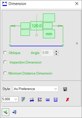
For a description of the Oblique option, see Linear Oblique.
|
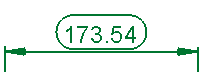
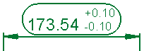
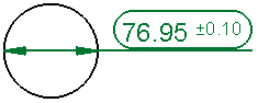
Inspection Dimension |
Surround dimensions with a rounded outline. This means that it is a dimension that should be inspected/verified after production.
|


|
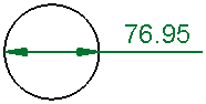
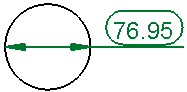
Minimum |
Create and position a dimension at the minimum distance between two points.
|
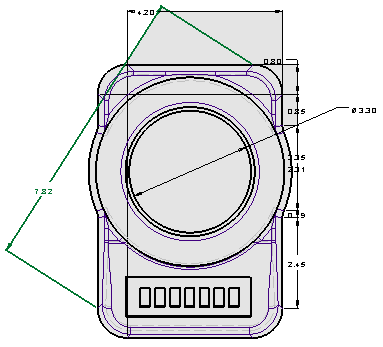
For environments that require the frequent use of the Minimum Distance Dimension, the option can be set as the default in Preferences > Drafting > General > Dimensions by selecting the Point to Point Dimension > Minimum Distance parameter.
|