|
|
Motion Simulation: Groups Tree
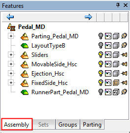
In the Assembly environment, the Groups tab is displayed. This contains the Groups Tree which is used for creating Groups in the Assembly Tree. The primary use of grouping parts together is for the Motion Simulation function; each group that you define can be given a different direction of motion.
Note: Grouping parts can also be useful outside of the Motion Simulation function. A Group provides an alternative to the Assembly Tree for hiding or showing a large number of parts in a single action. While Groups can be used much like an Assembly Set, the Groups Tree offers color and transparency control which is not provided by the Assembly Set pane. Also, unlike Sets, a part can only belong to one group at a time, and parts can be moved between groups by using drag and drop in the tree.
For Motion Simulation, the Groups Tree contains motion simulation groups of components. Each group represents a rigid body. The groups of components are fastened to each other such that no relative movement can exist between members of the same group. Components included in a motion simulation group don't need to be members of the same sub-assembly. Components can be assigned to the same group regardless of their hierarchic position in the assembly tree.
The default colors of the motion simulation groups are defined in the Preferences. These colors can be displayed during simulation and are controlled in the motion simulation dialog. You can also define the colors and render mode locally for each component in the Group Tree (these colors are coordinated with the assembly tree definitions and any change is applied to both trees).
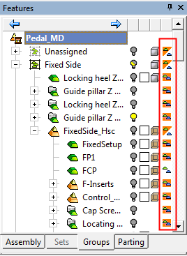
The Groups Tree structure is similar to that of the Assembly Tree; see Group Tree Popup Operations. An additional column of icons is displayed in the Groups Tree when Motion Simulation is open - see below.
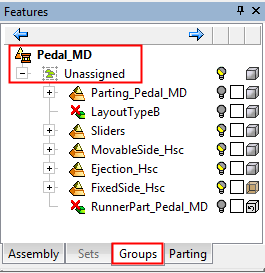
Initially, the Groups Tree contains the main assembly and the Unassigned group, as shown below:
|
Assembly tree: |
Groups tree - initial display: |
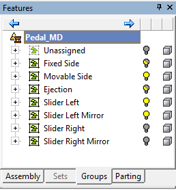
Groups tree - after relevant groups have been defined: |
|
|
|
|
Unassigned Group
By default, all components in the assembly are initially located in this group, in their original tree structure.
The Unassigned group is a system group that cannot be deleted or have a name change.
When creating new groups, selected components will be added to them automatically. Components can also be added to the new groups by dragging them from the Unassigned group
Groups Tree in Motion Simulation
When Motion Simulation is open, components can be assigned to groups by selecting them and then using the Middle Mouse Button to select a component of the group to which to attach them.
When Motion Simulation is open, an additional column of icons is displayed in the Groups Tree. This column of icons enables you to define whether a group or a component within a group should be ignored in the collision calculations.
|
|
|


|