|
|
New Injection Simulation  : Filling Simulation

Access: Open this function from the following location:
-
Select Analysis > Injection Simulation > New Simulation from the menu bar. Select the Filling Simulation option.
Start a new Moldex3D simulation.
The simulation and analysis of the injection molding process enables you to ensure optimal placement of injection points, and increase the quality of the manufactured part. The flow analysis tool displays a full 3D visualization of the molding process, providing the inner temperature and pressure of the cavity. You can evaluate the welding line, air traps, flow balance, cooling time, the number of gates needed, and the location of the gates.
Pick the melt entrance points and set the gate diameters.
Valid points that may be picked include point entities created in the Sketcher or geometrical points (End, Mid., etc.), all belonging to selected body or part. The point entities must coincide with the faces of the selected body, otherwise they cannot be picked.
For example:
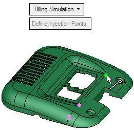
A figure is displayed on all selected points, as shown below. The figure axis is displayed normal to the face at the selected point. If the point belongs to more than one face, then a face is arbitrarily selected.
For example:
|
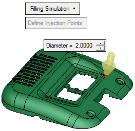
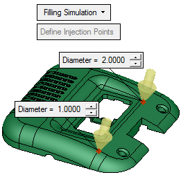
When you pick a point, the figure below is displayed at that point. This figure indicates a melt entrance point. At each melt entrance point, a label is displayed enabling you to control the gate diameter. |
Pick as many points as required: |
|
|
|
When finished, press OK ![]() in the Feature Guide. The third party application is opened with the Cimatron model already loaded and the melt entrance points as defined.
in the Feature Guide. The third party application is opened with the Cimatron model already loaded and the melt entrance points as defined.
|