|
|
Point Selection (Picking Points)

Access: Open this group of functions from one of the following locations:
-
Select the required point filter option in the Filter floating toolbar.
-
Select Edit > Point Filter from the menu bar. Select the required function.
The mouse is used as a tool for picking geometry. As you move over different types of geometric entities with the mouse cursor, the cursor symbol changes to indicate the type of entity to which you are pointing, thereby enabling you to pick a specific entity type.
There are numerous cursor symbols that are used to specifically indicate and pick points. There are also cursor point symbols that enable you to select a point by picking other entities. For example, picking two curves to select their intersection point. The various cursor point symbols are described below.
Note: When you 'pick' (click on) an entity, it becomes 'selected' and is displayed as selected in the defined color. You can define the color of selected entities (and also highlighted entities) in the Preferences under Tools > Preferences > General > Colors > Highlight and Select.
By default, you can always pick endpoints, midpoints, and center points. The cursor will tell you what kind of point you are selecting. For example:
|
Endpoint |
Midpoint |
Center point |
|
|
|
|


Additional point picking options are available from the following locations:
-
The Points tab of the Selection Filter.
-
The Point icons from the toolbar:

The following point picking options are available:
|
Selection Filter Name |
Function Icon |
Cursor Icon |
Description |
||||||||||||||||||||
|
End |
|
|
Enable/Disable the selection of End points (of curves). Pick the end point of a curve. |
||||||||||||||||||||
|
Middle |
|
|
Enable/Disable the selection of middle points (of curves). Pick the mid-point of a curve. |
||||||||||||||||||||
|
Center |
|
|
Enable/Disable the selection of center points (for circles and arcs). Pick the center point of an arc or circle. |
||||||||||||||||||||
|
3D Cone Edge |
|
This option enables you to easily define a center point on a non-circular edge with just a few clicks. Pick the 3D edges attached to a cylindrical face to select the center point projected onto the axis. The 3D Cone Edge filter is selected from the Selection Filter dialog when the Center radio button is selected in the Points tab.
|
|||||||||||||||||||||
|
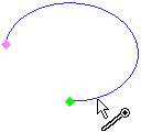
Close to Curve |
|
|
Enable/Disable the selection of points that are on curves or edges. Click on an edge or curve; the closest point to where you picked will be selected. |
||||||||||||||||||||
|
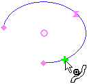
Close to Face |
|
|
Enable/Disable the selection of points that are on a face. Click on a face; the closest point on the face to where you picked will be selected. By using this option, points on imported STL files can also be picked. |
||||||||||||||||||||
|
Intersection |
|
|
Select a point of intersection between two curves or two axes. Pick two curves or two axes; their 2D or 3D intersection point will be selected. |
||||||||||||||||||||
|
Pierce |
|
|
Select a point where a curve pierces a face or plane. Pick a curve and a face or plane; the pierce point (of the curve through the face/plane) is displayed. A pierce point is also displayed if there is no real intersection between the curve and the face/plane - in this case, the pierce point is displayed on the extension of the picked curve at the point where it would have pierced the face/plane. If a pierce point is created on the extension of a picked curve, the type of extension created is as follows:
A curve (also an extension of a curve) can pierce a face at more than one point. The following cases define the type of occurrences and the location of the pierce point:
|
||||||||||||||||||||
|
TP Node |
|
|
Enable/Disable the selection of toolpath node points. Pick a segment of a tool motion (for NC only). |
||||||||||||||||||||
|
UCS Origin |
|
|
Enable/Disable the selection of UCS origin points. Pick a UCS to select its origin. |
||||||||||||||||||||
|
Point |
|
|
Create a point. Pick a predefined point. |
||||||||||||||||||||
|
Screen |
|
|
Enable/Disable the selection of points that appear anywhere in the display area. Click anywhere on the screen to create a point. |
||||||||||||||||||||
|
Key In |
|
|
Select a point by keying in its coordinates. Enter the required point's X, Y and Z coordinates. In the Sketcher, only the X and Y coordinates are available. |
||||||||||||||||||||
|
Delta |
|
Add delta on the main axes to a selected point. This is similar to Key In (mentioned above). The only difference is that you must first indicate a reference point using one of the point indication options above, and then enter the required point's X, Y, and Z coordinates as delta values (DX, DY, and DZ). In the Sketcher, only the X and Y coordinates are available. |
|||||||||||||||||||||
|
Stock Shape Point |
|
Enable/Disable the selection of stock shape points. Pick stock shape points (for NC only). |
|||||||||||||||||||||
|
Points Optional Selection |
|
Allow selecting and unselecting point filters simultaneously (as opposed to a single point filter at a time). When this toggle button is ON (selected), this enables the selection of multiple point filters, either from the Selection Filter or from the Points toolbar (shown above) or from the Floating Toolbar.
|


Note: Keyboard shortcuts for picking points are also available.
|