|
|
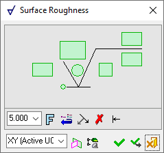
Surface Roughness PMI  : Dialog

Access: Open this function from one of the following locations:
-
Click the
button
in the toolbar. -
Select Tools > PMI > Surface Roughness from the menu bar.
Create PMI Surface Roughness symbols and assign them to appropriate entities.
Creating the PMI Surface Roughness symbols in the Modeling environment is very similar to creating the Surface Roughness symbols in the Drafting environment. The main differences are as detailed in PMI & Drafting.
|
The dialog for the symbol is displayed.
The symbol dialog is initially displayed grayed out until the symbol is positioned in the graphics window.
|
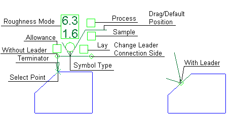
The image below shows an example of the symbol with each element labeled.
The dialog elements for this symbol are described below.
|
|
|
|
Annotate the symbol either in the dialog or in the graphics window (once the symbol has been positioned).
To edit (or to re-position) a symbol after it has been created:
Double-click the appropriate symbol. The relevant dialog associated with the symbol is displayed. This means that you are now in edit mode.
Edit the symbol elements and/or re-position the symbol as required.
Symbol Elements
|
Allowance |
Set the Machining Allowance value. This is the allowance made for extra material that will be machined off in a future step. |
||||||||||||||||
|
Change Leader Connection Side |
Change the connection point of the leader from one end of the base line to the other. |
||||||||||||||||
|
Drag/Default Position |
Drag the leader/symbol to a new location on the screen. |
||||||||||||||||
|
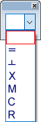
Lay |
Select the Lay symbol from the dropdown list. Lay is the predominant direction of the surface pattern and usually reflects the machining operation used to produce it. In many cases, manufactured surfaces have surface features which are directional. For example, turned cylindrical parts may have radial spiral grooves from the cutting tool. Lay symbols:
|
||||||||||||||||
|
Process |
Specify the production method. Up to 19 characters are allowed. |
||||||||||||||||
|
Roughness Mode |
Select the Mode from the dropdown list and set the values. Set the Mode and values:
|
||||||||||||||||
|
Sample |
Specify the surface sampling distance. Roughness parameters are determined based on a sample of the part of a specified length (up to 19 characters are allowed). |
||||||||||||||||
|
Select Point |
Drag the segment to a new location. |
||||||||||||||||
|
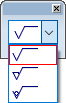
Symbol Type |
Select the Surface Roughness symbol type from the dropdown list. Surface Roughness symbols:
|
||||||||||||||||
|
Terminator |
Select the required terminator shape from the dropdown list. |
||||||||||||||||
|
With/Without Leader |
Toggle option to display or hide the symbol leader. |

Dialog Buttons
|
|
Set the required font size in the text. Default = 5 |
||||
|
|
Font: Select the font type in which to display the entity. The five most recently used fonts are displayed at the top of the list. |
||||
|
|
Restore Default: Reset all values and settings to the system defaults. |
||||
|
|
Branch Leader: Add additional leaders to the annotation.
|
||||
|
|
Delete Point: Delete the current entity from the annotation. |
||||
|
|
Switch Symbol Side: Flip the display of the annotation symbol to the opposite side of the selected entity.
If the normal at the picked point is normal to the M-View (defined plane), the symbol will be positioned according to the XY of the active M-view (plane,) and will be flipped along the X direction of the M-View.
|
||||
|
|
Active M-View: Change the projected plane to a preset orientation by selecting the appropriate M-View from the dropdown list. From this point onwards, the projection of this M-View is the default projection for all new entities. PMI M-Views can be added to this list as required. |
||||
|
|
Define Plane: Change the projected plane by picking a planar face, plane, or 3 points to define the active plane. From this point onwards, the projection of this plane is the default projection for all new entities. A plane of any orientation may be defined. |
||||
|
|
Selection Mode (Reference Entities): Pick reference entities (points, edges, etc.) from parts outside the active assembly or part. By default, if an assembly is activated, you can only pick reference entities from sub-assemblies or parts within the active assembly. Similarly, if a part is activated, you can only pick reference entities from the active part. The |
||||
|
|
OK: Accept the changes, perform the operation, and close the current dialog/task. |
||||
|
|
Apply: Accept the changes, perform the operation, and keep the current dialog/task open. |
||||
|
|
Cancel: Cancel all changes and close the dialog/task without saving the settings. |


|