|
|
PMI and Drafting
As mentioned in the introduction to PMI, in the Drafting environment drawings may get some or all of their PMI directly from the model, thereby, greatly reducing the time needed to create a drawing. ASME Y14.41-2003 allows both model-only and model-and-drawing methods of documenting a product. So either or both methods are acceptable ways to document a design.
PMI Integration within the Drafting environment
Differences between adding drafting symbols and annotations in PMI and in the Drafting environment
PMI Integration within the Drafting environment
In Cimatron, PMI is integrated within the Drafting environment in the following ways:
After you have created a drafting view, you can control the display of PMI in the view.
PMI can be saved as a Sheet Template.
PMI can be included in a new Sheet Template by loading the appropriate PMI template.
In the Electrode environment, as electrode assembly drawings do not have views (they have frames instead) and the view creation mechanism is automatic, an option to show PMI is available in the Preferences > Electrode > Assembly Drawing > Assembly General Settings dialog.
Differences between adding drafting symbols and annotations in PMI and in the Drafting environment
Adding PMI symbols and annotations (in the Modeling environment) is very similar to adding drafting symbols and annotations in the Drafting environment, even though modeling is a 3D environment and drawing is a 2D environment.
The main differences are as follows:
In Modeling, the PMI symbols and annotations are not automatically created by default. To approve the creation of the entity, either select the OK ![]() or Apply
or Apply ![]() button or press the MMBMMB anywhere out of the dialog.
button or press the MMBMMB anywhere out of the dialog.
The PMI symbols and annotations dialogs are similar to the equivalent dialogs in the Drafting application. However, there are some differences between the dialogs; these can be seen in the following comparison (in this case the PMI Surface Roughness function):
|
PMI Surface Roughness dialog in the Modeling environment: |
Surface Roughness dialog in the Drafting environment: |
|
|
|
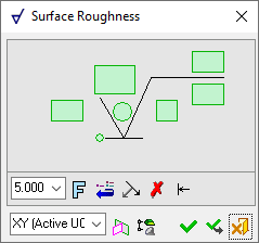
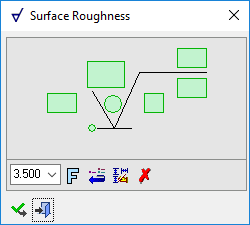
Some of the options that are available in the Drafting dialog are not available in Modeling. In Modeling, the following additional options are available (depending on the function selected):
PMI Dialog ButtonsPMI Dialog Buttons
The following buttons are specific to PMI functions:
|
|
Branch Leader: Add additional leaders to the annotation.
|
||||
|
|
Switch Symbol Side: Flip the display of the annotation symbol to the opposite side of the selected entity.
If the normal at the picked point is normal to the M-View (defined plane), the symbol will be positioned according to the XY of the active M-view (plane,) and will be flipped along the X direction of the M-View.
|
||||
|
|
Active M-View: Change the projected plane to a preset orientation by selecting the appropriate M-View from the dropdown list. From this point onwards, the projection of this M-View is the default projection for all new entities. PMI M-Views can be added to this list as required. |
||||
|
|
Define Plane: Change the projected plane by picking a planar face, plane, or 3 points to define the active plane. From this point onwards, the projection of this plane is the default projection for all new entities. A plane of any orientation may be defined. |
||||
|
|
Selection Mode (Reference Entities): Pick reference entities (points, edges, etc.) from parts outside the active assembly or part. By default, if an assembly is activated, you can only pick reference entities from sub-assemblies or parts within the active assembly. Similarly, if a part is activated, you can only pick reference entities from the active part. The |

Note: For additional information regarding dimension entities and dimension labeling, see the Drafting Online Help topic for the specific dimension type.
|