|
|
Cutter Tilt Control: Parameters
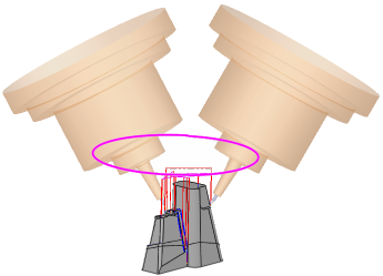
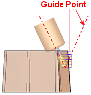
5-axis tilting is used in order to create a toolpath where the holder is collision free with the part, the stock, and the fixtures.
|
The current tool cannot mill certain areas. |
One option is to use a longer tool. |
The 5-axis option is to define a tilt angle and use the current tool. |
||
|
|
|
|
|
|
Parameters
|
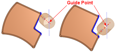
Additional Tilting Angle |
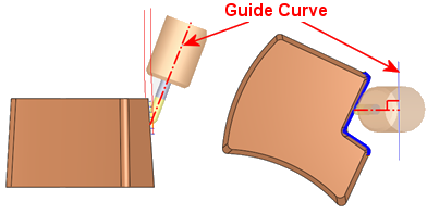
Set an angle offset from the solution calculated by the Guide. For example, if the Additional Tilting Angle is set as 5° and the calculated solution is 15°, the actual tilt angle will be 20°. Range = -45° to +45° This parameter is displayed if Tilting = To Guide. |
|||||||||||||||
|
Calculate Tilting |
Set the tilting calculation definition from the following dropdown options:
This parameter is displayed if Tilting = Auto. |
|||||||||||||||
|
Create UCS |
Create a UCS for an NC procedure. During the creation process, the cutter is continuously displayed in the appropriate orientation. This operation is available both within an open NC procedure and when no NC procedure is open. This parameter is similar to the UCS creation defined in Create UCS of the Clearance & UCS parameters. However, in this case, it only sets the UCS of the New Direction and not the UCS of the procedure (as in the Clearance & UCS). |
|||||||||||||||
|
Gouge Check |
When ON (selected), the system checks for and prevents any possible gouging by the cutter or holder. This parameter can be switched OFF (unselected) in cases where increased performance is desired and where the Preferred Angle can be defined to prevent gouging. However, in these cases, there is no holder gouge checking by the system and you should use the Machine Simulator to confirm the results. |
|||||||||||||||
|
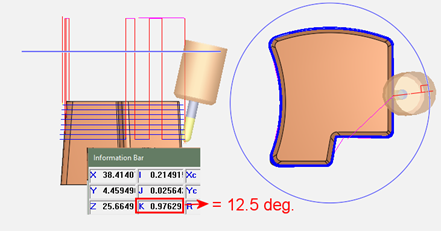
Preferred Angle |
The tilt angle (between the Z axis and the tool axis) preferred by the user when calculating the possible inclination of the tool. If the preferred angle is not suitable, a different angle may be used. In either case, the angle used is not more than the Maximum Angle. Range = 0° to 90° This parameter is displayed if Tilting = To Guide, Fixed Tilt, To Guide, Auto Tilt, or Auto. The following relation between the angles is observed: |
|||||||||||||||
|
Machine Preview |
Using the Machine Preview tool, in addition to the part, cutter and holder, you can also view the entire machine and fixtures, inside the NC programming environment. You can manually move the machine axes, considering the machine kinematics and travel limits, to an optimal orientation. Once found, an appropriate UCS is defined to be used for programing the procedure(s). This parameter is similar to the UCS creation defined in Machine Preview of the Clearance & UCS parameters. However, in this case, it only sets the UCS of the New Direction and not the UCS of the procedure (as in the Clearance & UCS). When the Machine Preview is accessed from here, the list of machines available for selection contains only 5-axis machines. |
|||||||||||||||
|
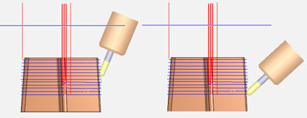
Maximum Angle (from Z Axis) |
The maximum angle (between the Z axis and the tool axis) allowed by the user when calculating the possible inclination of the tool.
Range = 0° to 90° This parameter is displayed if Tilting = To Guide, To Guide, Auto Tilt, or Auto. The following relation between the angles is observed: |
|||||||||||||||
|
Maximum Angle Change |
The maximum allowed tilt angle change. This parameter is displayed if Tilting = To Guide, To Guide, Fixed Tilt, To Guide, Auto Tilt, or Auto. |
|||||||||||||||
|
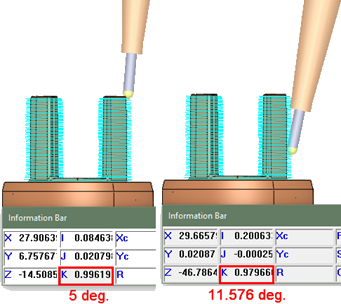
Minimum Angle (from Z Axis) |
The minimum angle (between the Z axis and the tool axis) allowed by the user when calculating the possible inclination of the tool.
Range = 0° to 90° This parameter is displayed if Tilting = To Guide. Generally, the following relation between the angles is observed: For the Auto 5X Tilt procedure, the following relationship between angles is observed: |
|||||||||||||||
|
New Direction |
Enables you to select a UCS from a dropdown list. If the New Direction is identical to the procedure’s UCS, a warning message is displayed and the procedure is not executed. This parameter is displayed if Tilting = Single Direction. |
|||||||||||||||
|
Tilting |
Set the tilting preference option.
The following tilting preference dropdown options are available:
|
|||||||||||||||
|
Tilting Priority |
Set the tilting priority definition from the following dropdown options:
In all cases, the used angle is not more than the Maximum Angle. Note: For the Auto 5X Tilt procedure, the Stable Tilt Angle and Minimize Tilting options are the only available Tilting Priority options. The Preferred Angle option is not available. |
|||||||||||||||
|
Tool Axis Direction |
Set the cutter axis direction from the following dropdown options:
This parameter is displayed if Tilting = To Guide, To Guide, Fixed Tilt, or To Guide, Auto Tilt. |
|||||||||||||||

Notes:
-
Cutter Tilt Control is only displayed if the toolpath is 5-axis.
-
To use the Cutter Tilt Control parameters, a ball cutter with a holder must be defined for the procedure.
Convert to 5X Operational NotesConvert to 5X Operational Notes
To use the Convert to 5X > 5X Tilt procedure, the following are the prerequisites and operational requirements:
Prerequisites
-
An input procedure must exist. It must be calculated and use a ball tool.
-
The input procedure must use a single cutter (not multi cutters).
-
The tool axis of all motions of the input procedure must be parallel to the Z direction of its UCS.
-
The input procedure and tilting procedure must both use a ball tool with an identical diameter.
-
The 5X tilting procedure must be in a 5X toolpath.
Re-calculating the input procedure
-
The input procedure may be recalculated.
-
If the input procedure is changed without changing its cutter diameter, the tilting procedure is suspended.
-
If the input procedure is changed and a different cutter tip is used, the tilting procedure receives a G flag. In this case, the tilting procedure cutter is not changed automatically.
Changes to the input procedure
-
The input procedure may change for one of the following reasons:
-
The motions of the input procedure are changed (re-calculated, deleted, etc.).
-
The input procedure is deleted, so another procedure automatically becomes the input procedure.
-
A new procedure is inserted between the input procedure and the tilting procedure, so it becomes the new input.
-
-
In all these cases, the motions of the tilting procedure are deleted and the procedure becomes suspended.
-
If the relation between the new input procedure and the tilting procedure does not meet the required prerequisites (see above), the tilting procedure receives a G flag.
Operations on the input procedure
-
The following are not performed on the input procedure:
-
You can copy, paste, cut or delete both the input and the tilting procedures.
|