Clearance: Create UCS
![]()
![]()
Access: Open this function from one of the following locations:
-
When a relevant procedure is open: in the Clearance & UCS parameter table, press the Access button adjacent to the Create UCS parameter. The New UCS Creation dialog is displayed.
-
From Remachine Segments > Edit Segments Dialog. The Direction Definition dialog is displayed.
Note: UCSs can also be created in the Machine Preview environment.
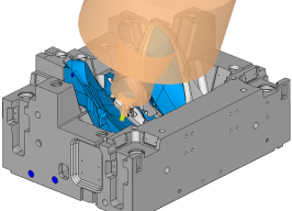
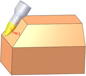
Create a UCS for an NC procedure. During the creation process, the cutter is continuously displayed in the appropriate orientation. This operation is available both within an open NC procedure and when no NC procedure is open.
When machining deep cavities, large cores or prismatic parts, it is common to use 3+2 axis positioning in order to be able to employ shorter and more robust tools and to achieve faster and better machining. However, it is often a process of trial and error to determine the optimal orientation.
Cimatron provides dedicated functionality in this regard. It offers significant time savings by enabling you to repeatedly experiment and preview the orientation of the tool and its holder prior to creating the UCS.
This functionality will visually place any cutter from your cutter library on the selected point. This lets you check cutter positioning and clearance before you start programming the toolpath. While the cutter is being previewed, the tilt angle can be adjusted or fixed. Selecting other points will allow you to check the cutter at this angle in various positions, either with or without the remaining stock, providing a quick way to find the optimal programming UCS for 5-axis machining as well as 3-axis machining on angles.
This functionality is available in all toolpath types and for each procedure except Transformation, Automated Drill, Drill and Connection.
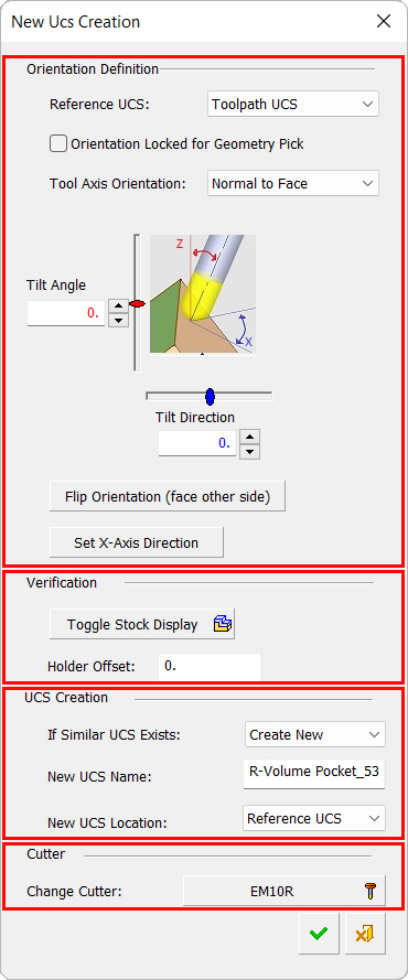
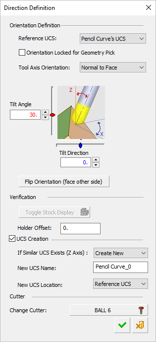
When this option is invoked, the New UCS Creation dialog is displayed. A very similar dialog is displayed when invoked from Remachine Segments > Edit Segments Dialog; this displays the Direction Definition dialog.
|
New UCS Creation dialog |
Direction Definition dialog displayed when invoked from Remachine Segments > Edit Segments Dialog |
|||||
|
|
|
Orientation Definition: Set the desired orientation. Verification: Visual check for collisions. UCS Creation: Creation rules; position and name. Cutter: Check with other cutters/holders.
|
||||
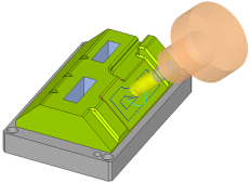
Select a point (the cutter is displayed at the point) and set the parameters.
When a new UCS is defined and you press the OK button at the bottom of the dialog, this new UCS becomes the active UCS of the procedure (the UCS Name parameter in the Clearance & UCS table, is updated with the new UCS name). All subsequent settings are done according to the new UCS.
Parameters
When this option is invokedinvoked, the tool tip is positioned on the Reference UCS (set as the top of the New UCS Creation dialog). When you pick a point, the tool is positioned on the picked point
|
Reference UCS |
The Reference UCS determines the base direction of the new UCS and is the reference for the new UCS orientation. Select a reference UCS from the dropdown list of options. When the dialog is invoked from the parameter table, the following options are available:
When the dialog is invoked from the menu bar, the following options are available (see the notes below):
|
||||||||||||
|
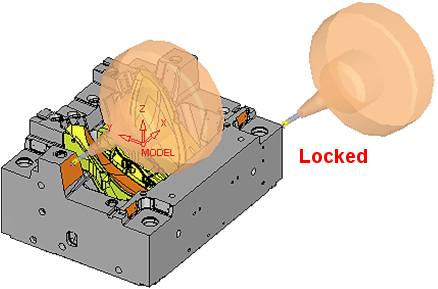
Orientation locked for geometry pick |
When this checkbox is marked When this checkbox is OFF Default = OFF
|
||||||||||||
|
Tool Axis Orientation |
This parameter is grayed out if the orientation lock checkbox (the previous parameter) is ON Changing the tool axis may reset any changes you have already made to the machine X axis. |
||||||||||||
|
Normal to Face |
Create a UCS such that the tool axis is normal to the face it mills. The tool orientation is normal to the face at the selected point. The Tilt Angle and Tilt Direction are changed accordingly, since they are measured from the Reference UCS.
For the Tilt Angle and Tilt Direction, see Tool Axis Control below. |
||||||||||||
|
Tangent to Face |
Create a UCS such that the tool axis is tangent to the face it mills. The tool orientation is tangent to the surface at the selected point. The Tilt Angle considers the cutter's shape when calculating the required angle.
Circle Segment cutters mill best with the largest radii of the cutter tangent to the surface it mills.
For Circle Segment - Barrel cutters, the best slope angle range for milling is displayed for a specific cutter below the cutter image in the Cutters and Holders dialog. This angle range specifies the angle between the cutter axis and the normal of the face it mills and indicates the minimum and maximum slope angles of faces that can best be milled by a specific cutter.
These minimum and maximum slope angles may be used in relations using their respective short names: minslope and maxslope. This range of best slope angles for milling is taken into account when calculating the Tilt Angle. |
||||||||||||
|
Fixed Tilt Angle |
Create a UCS such that the tool axis is fixed in relation face it mills. Similar to Normal to Face, however, the Tilt Angle does not change. This means that the tilt angle is fixed to the existing value and the Direction Angle is the angle of the face normal.
|
||||||||||||
|
Swarf by One Point |
Depending on the location of the selected point, one of the following occurs:
|
||||||||||||
|
Swarf by Two Planes |
Select two points on planar faces.
Note: The tool tip for the touch point is calculated after the orientation is calculated. |
||||||||||||
|
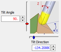
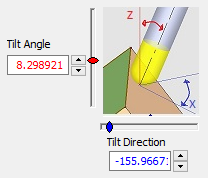
Tool Axis Control |
Set the Tilt Angle and Tilt Direction, either by entering
values or by using the appropriate slider. When the angles are changed,
the tool is rotated around its tip. The sliders and value fields are color
coded for user assistance.
Tilt Angle/Direction ExamplesTilt Angle/Direction Examples
|
||||||||||||
|
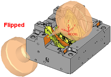
Flip Orientation |
Change the direction of the selected face 180 degrees. This change is reflected in the Tool Axis Control area, above.
|
||||||||||||
|
Set X-Axis Direction |
Control and change the direction of the X-axis manually. Any subsequent changes to the tool axis may reset the machine X axis. |
||||||||||||
|
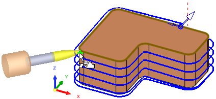
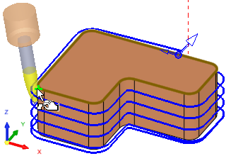
Toggle Stock Display |
Toggle to hide/show the stock. This can be used to visually verify that a collision is avoided with the stock. See the examples below.
|
||||||||||||
|
Holder Offset |
Set the holder safety distance to visually verify that a collision is avoided with the stock. |
||||||||||||
|
If Similar UCS Exists |
If a similar UCS exists (having the same Z-axis), select from the following options:
|
||||||||||||
|
New UCS Name |
Set the name for the new UCS. The default name is <procedure name>_<procedure number> for example for Rough Spiral: R-Spiral_13. |
||||||||||||
|
New UCS Location |
Select the location of the new UCS from the following options (see the examples below):
|
||||||||||||
|
Change Cutter |
Change the cutter. This displays the cutter table, enabling you to change the cutter, including creating a new cutter. |
||||||||||||


Notes:
-
If multiple cutters are used in the procedures, the active cutter is displayed and cannot be changed.
-
When the dialog is invoked from the menu bar, the following occurs:
-
-
The Reference UCS options are Model UCS and Active UCS, (default = Active UCS).
-
The stock display is grayed out.
-
The default New UCS Name is UCSxx, as if it were created as a new normal feature.
-
The cutter for the operation is the active cutter. If this does not exist, one is created.
-
Dialog buttons
|
|
OK - accept and save the changes and close the dialog. In this case, the new UCS is created with the following characteristics:
|
|
|
Cancel - reject the changes and close the dialog without saving. |