|
|
Machine Preview 

Access: Open this function from one of the following locations:
-
When no procedure is open: Select Wireframe > Datum > By Machine Preview from the menu bar.
-
When a procedure is open: Click the Machine Preview button in the Clearance & UCS parameter table.
Using the Machine Preview tool, in addition to the part, cutter and holder, you can also view the entire machine and fixtures, inside the NC programming environment. You can manually move the machine axes, considering the machine kinematics and travel limits, to an optimal orientation. Once found, an appropriate UCS is defined to be used for programing the procedure(s).
This function enables you to preview the Machine while defining the Setup on the machine and the milling direction of each procedure.
Defining a relevant UCS for 3+2X operations, especially in deep cavity or narrow area parts, may be problematic. In some cases, a UCS is defined and later on while simulating or machining it transpires that the machine cannot reach the desired position or even worse, a collision of a machine component with the part or stock.
ExampleExample
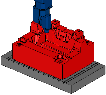
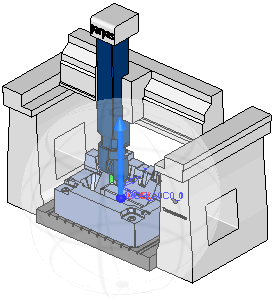
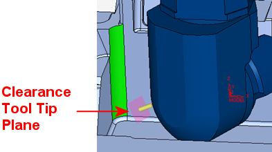
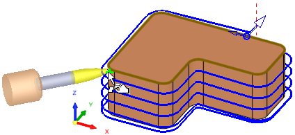
In the example below, a procedure is set to create a local operation on the green corner face. Since the part is quite large it is impossible to do that in a vertical direction without having the machine head collide with the part. Machine Preview can be used to find a safe orientation for this job.
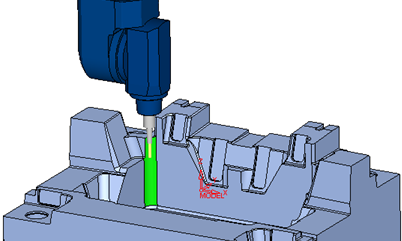
When this operation is invokedinvoked, the Machine Preview dialog is displayed. The Machine Preview, Machine Parameters, and Machining Simulation tools present similar parameters.
|
|
The Machine Preview enables you to:
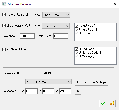
The Machine Preview dialog shows the same machine that was defined in the NC Setup, the same Reference UCS, and the same Setup Zero values. All these settings can be changed or initially set if the NC Setup is not in use. |
Parameters
|
Material Removal |
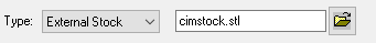
When this checkbox is marked Select the type of stock to be used from the drop-down list.
|
||||||||||||||||||
|
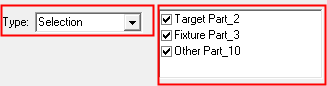
Check Against Part |
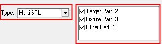
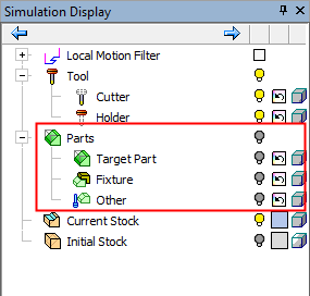
When this checkbox is marked Select the type of part to be used from a drop-down list of options.
|
||||||||||||||||||
|
Tolerance |
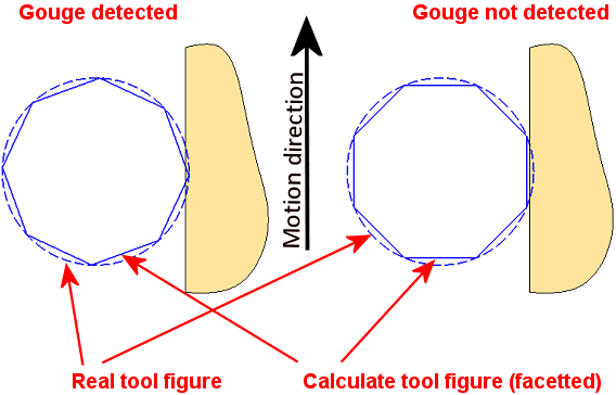
Define the toolpath tolerance for the simulation. This is also used as a threshold for gouge checking as any gouges are displayed in red. The default is 0.01 mm / 0.0004 inch. Note that this tolerance affects a number of things:
The fact that the tool is actually considered as a polygon rather than its true round shape is the same in most simulators. This might cause some detection accuracy issues. Depending of the angle of the polygons and the motion direction in reference to the part geometry, some gouges will not be detected. Note that in reality the calculated representation of the tool is not as coarse as seen in the below image. This image is a schematic representation of the accuracy issues.
|
||||||||||||||||||
|
Part Offset |
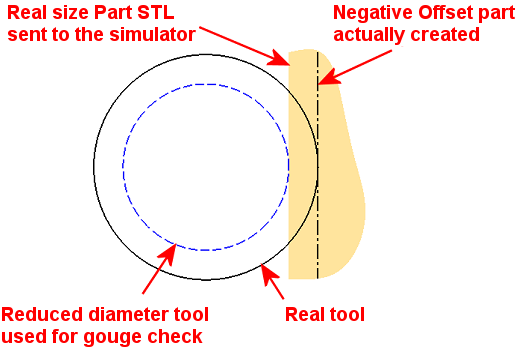
Sets a safety clearance for the collision check between machine components and the part. Define the part offset against which you wish to perform the gouge checking and remaining material reporting. The default is 0 mm / inch. The Part STL file is always created in the exact size it is designed in Cimatron. When an offset other than zero is set, the simulator engine imitates a different Part by changing the tool diameter accordingly.
|
||||||||||||||||||
|
NC Setup Utilities |
When this checkbox is marked Utility procedures may change the configuration of the machine. Therefore, by applying them in the NC Setup Utilities section of the dialog prior to the run, any configuration changes are taken into account. If there are no Utility procedures, the NC Setup Utilities section of the dialog is empty and dimmed. |
||||||||||||||||||
|
Reference UCS |
This field displays the settings as defined in the NC Setup; this can be changed if required. Define the Reference UCS on which the current operation is to be based from a dropdown list of all the UCSs in the current ELT file. This Reference UCS enables you to define a different UCS as required; for example, when a different clamping situation is necessary, typically "Machining from TOP" and "Machining from BOTTOM". In the example below, the orange surface will be machined from above and the green area from the side. Because it is machined from another orientation, the green surface toolpath has different motion limits, which are based on its own separate UCS.
The Reference UCS is also important in the posting process where it defines the reference point and reference axes direction for the whole posting process. All other UCS's and tool points are defined relative to the Reference UCS. The Reference UCS is also used by the Setup
Zero.
The default value is the active UCS. |
||||||||||||||||||
|
Machine |
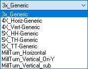
This field displays the name of the machine which is selected for the machining process. If a machine was defined in the NC Setup, the same machine is displayed; however, it is possible to select a different machine. Select the type of CNC machine to be used from a dropdown list of options. For example:
Note: To add CNC machines to the library, contact your Cimatron Provider or Reseller. |
||||||||||||||||||
|
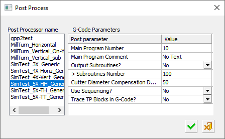
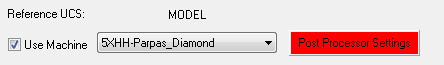
Post Processor Settings |
Define the post processor settings. This option displays the post processor settingspost processor settings dialog, enabling you to change them as required.
Each post has an interaction setting which influences the output. The Post Processor Settings button enables access to the post interaction. If this button is displayed in REDdisplayed in RED, this means that the post settings are not complete (either they do not exist or they do not fit the machine - for example, a 3-axis post to a 5 axis machine). Click and set the post processor settings.
|
||||||||||||||||||
|
Setup Zero |
This field displays the settings as defined in the NC Setup; this can be changed if required. The numbers displayed here represent the position of the part (to be machined) on the machining center, relative to a predefined UCS. You can modify the offset values to adjust the part location within the machine envelope, enabling optimal use of the available space. Define the XYZ machine zero in the coordinate system, either by directly entering the XYZ coordinates or by using the adjacent The coordinates are passed to the Post Processor in the BEGINNING OF TAPE block (X_MACH, Y_MACH, Z_MACH).
This definition is needed for Machining Simulation, but also affects the actual G-Code if being used by the specific post processor. Modifying the Reference UCS at any point (or switching between a GPP post processor to a GPP2 post processor) does not affect the numbers. Once calculated (or keyed in), they stay "as is". For GPP2, setting the displayed numbers at (0,0,0) effectively tells GPP2 to ignore them (since it means that the machine zero point is at the REF UCS zero point). This is equivalent to setting M5_USE_MACH (5X machine definition variable) to FALSE inside the post processor. |


Click OK ![]() to activate the Machine Preview environment.
to activate the Machine Preview environment.
The Machine Preview application is actually a reduced Machine Simulator environment. Because there is no toolpath to be simulated and no stock, the Simulation Control, Stop Conditions, Simulation Report, Motion List, and Stock Analysis are not relevant, therefore they are inactive in the Simulator Guide.

The Axes Control dialog that is shown is also similar to the same dialog in the Machine Simulator, with the exception of the Machine Preview related buttons at the bottom of the dialog.
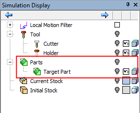
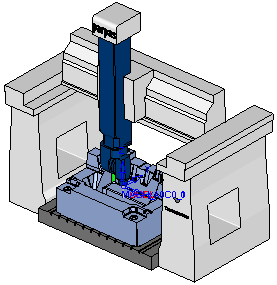
The graphics area shows the entire machine. The part is placed on the machine table based on the Reference UCS and the Setup Zero values. The initial tool orientation is aligned with the orientation of the current procedure UCS; in the example above, it is vertical. The tool mounted on the machine spindle is the procedure tool. The machine axes are positioned in a Safe Position as defined in the machine post processor.
Important:
-
All the types of collision checks (in feed motions) of the Machine Simulator are active in all the modes of the Machine Preview (all the machine axes movements, manual, and automatic are considered as feed movements).
-
None of the gouge checks of the Machine Simulator are active in the Machine Preview (GOUGE means the CUT portion of the cutter penetrates the Part model, all other interference situations are considered as collisions).
-
In the case of a collision, the colliding objects are colored in RED. Example:Example:
-
The GPP2 Post Processor uses the angle values in NC Setup, Machine Simulator, Machine Preview, and Post Processing only when the Machine and Post Processor names match.
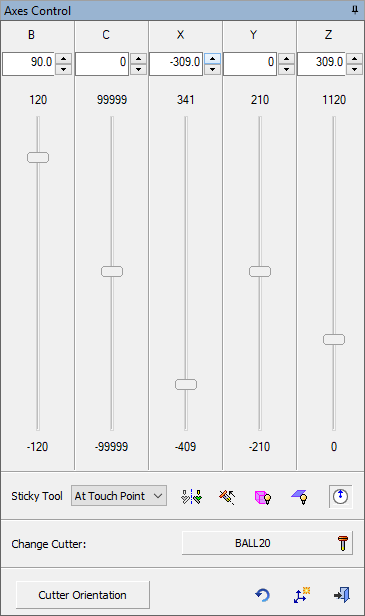
Axes Control dialog
The Axes Control dialog is displayed:
|
|
In addition to being able to drag the axes on the graphics screen, they can also be moved in the Axes Control dialog. It is possible to drag an axis slider or change the value in the current position field on top. As in the Axes Control dialog of the Machine Simulation, sliders are displayed for all the relevant axes. When an axis is changed, this is reflected in the simulation window. At the top of each axis a text box enables you to enter an axis value. These numbers are updated when moving the sliders. The axis limits of each axis are displayed at each end of the sliders. If an axis value entered in a text box is outside the axis limits, it is automatically modified to the nearest limit value and the relevant limit value is displayed in RED. Axes Control and Sticky Tool: Movement behavior differs between the rotary and linear axes. The linear axes move on their own. A rotary axis movement may affect some of the other axes as well. If the Sticky Tool option is not set as Off (see below), in order to maintain the contact with the picked point, every rotation must be compensated with some linear and sometimes angular movements. You can change the tool orientation (vs. the part) in the following ways:
|
Parameters
|
Sticky Tool |
Choose whether and how the tool maintains contact with the picked point. See the Axes Control and Stick Tool explanation above (in the general description of the Axes Control dialog). The following options are available:
|
|||||||||||||||||||||||||||||||||
|
|
Flip Solutions: In many cases, there are usually two potential solutions for the machine rotary axes. The Flip Solutions button flips enables you to flip between these two solutions. This button is disabled when two solutions are not available. |
|||||||||||||||||||||||||||||||||
|
|
Retract Along Tool Axis: This enables you to check a retract position. This enables you to check how much clearance there is for retraction in the current orientation, considering the machine linear limits and possible collisions. The Retract dialog is displayed.
|
|||||||||||||||||||||||||||||||||
|
|
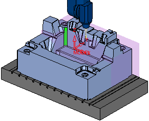
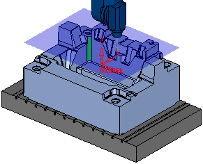
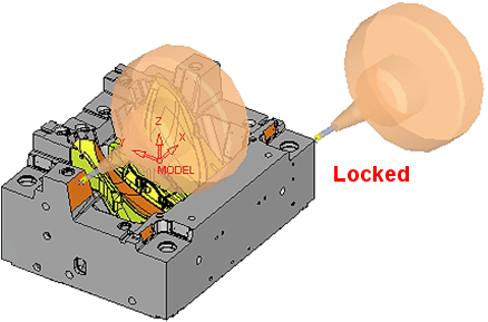
Hide/Show the reachable region of the cutter tool tip: A transparent rectangle appears showing the reachable space of the tool tip in its current orientation without exceeding the machine limits. This enables you to see which areas might be out of reach.
The box location is updated with any change of any axis (e.g. a change in the head rotary axis). |
|||||||||||||||||||||||||||||||||
|
|
Hide/Show clearance plane: This hides/shows the original clearance plane of the procedure (according to the UCS and Clearance Z value of the procedure). This indicates if it is too high considering the machine Z maximum limit.
|
|||||||||||||||||||||||||||||||||
|
|
Hide/Show tool axis arrow: This hides or shows the tool axis arrow and the transparent sphere. The arrow direction is displayed on the center line of the cutter.
|
|||||||||||||||||||||||||||||||||
|
Change Cutter |
The Change Cutter button shows the Cutter which is currently in the machine spindle. If other cutters are planned to be used for machining this area in the same orientation, they can be checked as well. If required, click the Cutter button to open the Cutters and Holders dialog and select a different cutter. When the cutter changes, the machine linear axes also change in order to compensate for the different length. Note: You can also set different safety clearance values for the fixtures and the various cutter sections. This can be done in the Simulation Options dialog, in the Simulation and Tool tabs, respectively. |
|||||||||||||||||||||||||||||||||
|
Cutter Orientation |
Define the cutter orientation. This displays the Cutter Orientation Definition dialog (see below). This button is enabled when the machine has at least one rotary axis, otherwise it is disabled. |
|||||||||||||||||||||||||||||||||
|
|
Reset: This restores the initial load position and settings. |
|||||||||||||||||||||||||||||||||
|
|
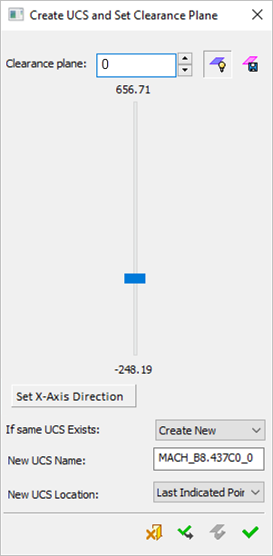
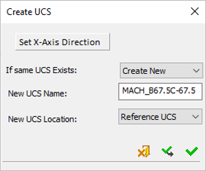
Create UCS and Exit: Create a UCS and exit the Machine Preview environment. Depending on how the Machine Preview was invokedinvoked, a new clearance plane value can also be set in the displayed dialog. The dialog that is displayed and the operations that are available depend on how the Machine Preview was invokedinvoked:
Parameters
|
|||||||||||||||||||||||||||||||||
|
|
Exit: Exit the operation and close the dialog/task. |


Cutter Orientation
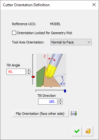
Define the cutter orientation. The Cutter Orientation button (in the Axes Control dialog above) is enabled when the machine has at least one rotary axis, otherwise it is disabled. When clicked, this displays the Cutter Orientation Definition dialog with the sliders and parameter values reflecting the current cutter orientation.
|
|
Important:
|
Parameters
|
Reference UCS |
This displays the reference UCS used. This is informative only. Notes:
|
||||||||
|
Orientation Locked for Geometry Pick |
When this checkbox is marked When this checkbox is OFF Default = OFF
|
||||||||
|
Tool Axis Orientation |
This parameter is grayed out if the orientation lock checkbox (the previous parameter) is ON
|
||||||||
|
Tool Axis Control |
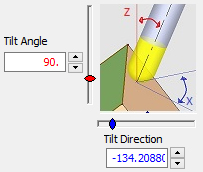
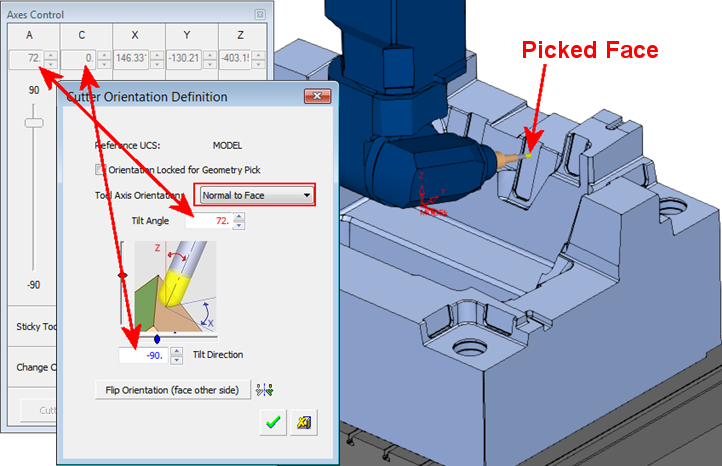
Set the Tilt Angle and Tilt Direction, either by entering values or by using the appropriate slider. When the angles are changed, the tool is rotated around its tip. The sliders and value fields are color coded for user assistance.
Tilt Angle/Direction ExamplesTilt Angle/Direction Examples
These controls can also be set in the Axes Control dialog. When the controls are set in the Cutter Orientation Definition dialog, they are translated to the machine angles in the Axes Control dialog. In this example, the Tool Axis Orientation is set to Normal to Face and a face is picked (as shown). Note that the Tilt Angle is translated to the machine A angle; in this case they are both identical (72°). The Tilt Direction of -90° is translated to 0° for the machine C axis (this depends on the machine configuration and rotary limits).
|
||||||||
|
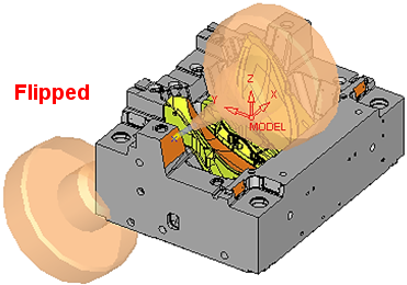
Flip Orientation |
Change the direction of the selected face 180 degrees. This change is reflected in the Tool Axis Control area, above.
|
||||||||
|
|
Flip Solutions: In many cases, there are usually two potential solutions for the machine rotary axes. The Flip Solutions button flips enables you to flip between these two solutions. This button is disabled when two solutions are not available. |
||||||||
|
|
OK: Accept the changes, perform the operation, and close the current dialog/task. The cutter and machine remain in the current orientation and position. |
||||||||
|
|
Cancel: Cancel all changes and close the dialog/task without saving the settings. The orientation and position of the machine is reinstated to the state before the Cutter Orientation Definition dialog was opened. |
||||||||


|