|
|
Pocket Manager: Pocket Table Parameters

Access: Open this function from the following location:
-
Click the Show The Pocket Table option in the Pocket Manager dialog.
When ON, display the Pocket Table showing all the detected pockets. Each row in the table represents one pocket.
The NC Pocket Table dialog is displayed.
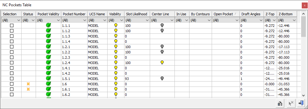
The table shows all the detected pockets; the total number is displayed in the All NC Pockets section of the Pocket Manager dialog.
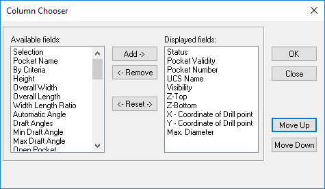
To configure which of the available columns are visible and to customize the Pocket Table, click on the Column Chooser button ![]() .
.
The following parameters are available as column headers in the Pocket Table:
The table below is sortable; it has clickable headers that sort the table by the clicked column. The table is initially sorted by Column #.
| Column # | Parameter | Explanation |
|
1 |
Selection |
The pocket is selected for operation. |
|
2 |
Status |
Edited, New. |
|
3 |
Pocket Validity |
Valid or Invalid. |
|
4 |
Pocket Number |
The pocket number represents the pocket hierarchy. |
|
5 |
UCS Name |
The UCS of the pocket. |
|
6 |
Pocket Name |
The user-defined name of the pocket. |
|
7 |
Visibility |
Pocket visibility. |
|
8 |
In Use |
Used by at least one procedure. |
|
9 |
Source for Expanding |
The pocket is the source for an expanded pocket. |
|
10 |
By Contours |
The pocket is defined by contour. |
|
11 |
By Expanding |
The pocket is defined by expanding other pockets. |
|
12 |
By Criteria |
The pocket is defined by criteria. |
|
13 |
Z-Top |
The Z-Top of the pocket. |
|
14 |
Z-Bottom |
The Z-Bottom of the pocket. |
|
15 |
Height |
The height of the pocket. |
|
16 |
Over All Width |
The total width of the pocket. |
|
17 |
Over All Length |
The total length of the pocket. |
|
18 |
Width Length Ratio |
Width to length ratio. |
|
19 |
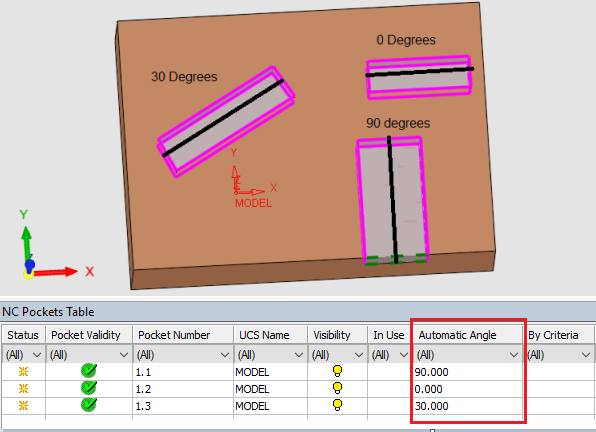
Automatic Angle |
The angle between the main axis of the pocket (along the largest dimension of the pocket) and the X axis. Additional InformationAdditional Information A pocket has an imaginary 'main axis'. This is a line along the largest dimension of the pocket (drawn as a solid black line in the image below). The Automatic Angle is the angle between that line and the X axis.
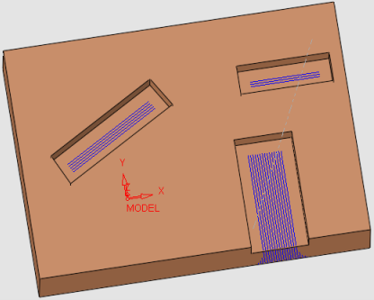
This is an informative field, however if you mill Parallel (Rough or Finish), you may wish to use this angle as the machining angle. In addition, when using any of the Finish procedures with the following parameter settings, the milling will be performed in the direction of the Automatic Angle: Machining Method = Parallel Milling Direction Type = By Local Geometry
|
|
20 |
Simple Pocket |
The pocket is designated as a Simple Pocket. A Simple Pocket is a pocket that can be milled by 2.5-axis procedures. A simple pocket has a single draft angle, no chamfer or fillet at the top or bottom, no multi radius fillets at the bottom (it can have a single fillet at the bottom) and no cylindrical corners. |
|
21 |
Draft Angles |
The number of draft angles in the pocket. |
|
22 |
Min. Draft Angle |
The minimum angle of the draft angle walls. |
|
23 |
Max. Draft Angle |
The maximum angle of the draft angle walls. |
|
24 |
Open Pocket |
The pocket is open. |
|
25 |
Totally Open |
The outer contour of the pocket is totally open. |
|
26 |
Through Pocket |
Through pocket – no floor. |
|
27 |
Circular Pocket |
The pocket is circular. |
|
28 |
Sharp Corners |
The pocket has sharp corners. |
|
29 |
Cylindrical Corners |
The corners of tapered walls are cylindrical and not conic. |
|
30 |
Top Chamfer |
The pocket has a top chamfer. |
|
31 |
Top Chamfer Angle |
The angle of the top chamfer. |
|
32 |
Top Chamfer Height |
The height of the top chamfer. |
|
33 |
Top Fillet |
The pocket has a top fillet. |
|
34 |
Top Fillet Radius |
The radius of the top fillet. |
|
35 |
Top Fillet Height |
The height of the top fillet. |
|
36 |
Bottom Chamfer |
The pocket has a bottom chamfer. |
|
37 |
Bottom Chamfer Angle |
The angle of the bottom chamfer. |
|
38 |
Bottom Chamfer Height |
The height of the bottom chamfer. |
|
39 |
Bottom Fillet |
The pocket has a bottom fillet. |
|
40 |
Bottom Fillet Radius |
The radius of the bottom fillet. |
|
41 |
Bottom Fillet Height |
The height of the bottom fillet. |
|
42 |
Max. Diameter |
The maximum diameter that can fit in the pocket. |
|
43 |
X - Coordinate of Drill Point |
The X coordinate of the drill point. |
|
44 |
Y - Coordinate of Drill Point |
The Y coordinate of the drill point. |
|
45 |
Number of Faces |
The number of faces in the pocket. |
|
46 |
Min. Radius |
The minimum radius within the pocket. |
|
47 |
Template |
The name of the template used to create a procedure to machine the pocket. If multiple templates are selected, "Many" is displayed; if no template was selected, the cell is blank. |
|
48 |
Tapered Pocket |
The pocket has at least one tapered wall. |
|
49 |
Comment |
User comment. |
|
50 |
Slot Likelihood |
This displays the likelihood that the pocket is a slot-shaped pocket, ranging
between zero (not a slot-shaped pocket) and 100 (definitely a slot-shaped
pocket). |
|
51 |
Center Line |
This displays the visibility (hide/show) status of the center line (skeleton)
of a pocket. |
|
52 |
Misc. 1 |
Miscellaneous #1 |
|
53 |
Misc. 2 |
Miscellaneous #2 |
|
54 |
Misc. 3 |
Miscellaneous #3 |
|
55 |
Misc. 4 |
Miscellaneous #4 |

|