NC Preferences > Default Values

Access: Invoke this function from one of the following locations:
-
Select the Preferences button
 from the Quick Access Toolbar, or
 -
Select Tools > Main Tools > Preferences from the menu bar.
Navigate to NC > Default Values.
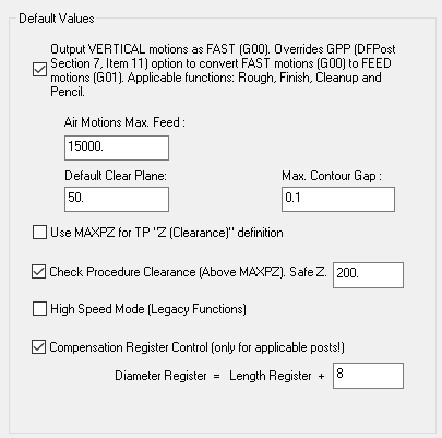
Define the default NC values.
The Default Values dialog is displayed.
Interaction
-
Set the required default values.
|
Output VERTICAL motions as FAST (G00) |
This parameter controls the output the system generates during connection motions for the following functions: Rough, Finish, Cleanup, and Pencil. The following occurs:
|
|
Air Motions Feed |
Define the rate at which rapid motions will be performed. This value will be used if Rapid is selected for Air Motions in the Machine Parameters dialog. (If Feed is selected, the default rapid rate of the tool (G01) will be used. This rate is internal to the tool and cannot be changed). |
|
Default Clear Plane |
The clearance plane used when defining a Toolpath. |
|
Max. Contour Gap |
If the gap between two contours is smaller than this tolerance value, the contours will be connected. |
|
Use MAXPZ for TP "Z(Clearance)" definition |
Use MAXPZ for toolpath Z Clearance definitions. |
|
Check Procedure Clearance (Above MAXPZ) |
Check that the procedure's clearance is above the part. The system compares the procedure clearance value to MAXPZ. If clearance is too low, an appropriate warning message is displayed. |
|
Safe Z Above MAXPZ |
Define a safe Z distance above the highest Z of all the faces in the file. |
|
Use High Speed Mode (Legacy Functions) |
Select this box to enable the following parameters in NC Legacy procedures: Contour Milling - Profile In Milling Mode - Trochoidal Milling Surface Milling - Parallel cut - Bidir - In Connection Type - Loops Outward; Loops Inward; Golf Club. Surface Milling - Spiral cut In Connection Type - High Speed Connection Surface Milling and Volume Milling - Spiral cut - Outside In In Corner Milling - All Loops Volume Milling - Spiral cut - Outside In - Mill Finish Pass - ON In Corner Milling - Rough Round Loops. Surface Milling - By layers HSM Layer Connect In Connection Type - High Speed Connection Parallel cut - Bidir In Connection Type - Loops Outward; Loops Inward; Golf Club |
|
Compensation Register Control
|
Enable Compensation Register Control. This can only be used by appropriate Post Processors.
If this option is selected, additional parameters are displayed:
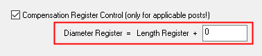
These parameters are used when defining cutters and enable you to define the Diameter Compensation of a tool in relation to the Length Compensation + a numeric value.
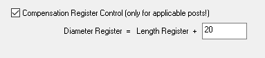
The Length Compensation and Diameter Compensation are defined in the Cutters and Holders dialog, however, the numeric value, if it is > 0, ensures a constant difference between the Diameter Compensation and the Length Compensation.
For example, if the numeric value in the Preferences is changed to 20, the Diameter Compensation will always be 20 more than the Length Compensation.
Initially, to support files prior to Cimatron 8.0, the default numeric value is set to 0 so that the Diameter Compensation = Length Compensation.
|
-
Press the appropriate approval option.