|
|
Create Stock  : Bounding Box

Access: Open this function from one of the following locations:
Select the toolpath for which the stock will be created, and then create the stock in one of the following ways:
-
Select NC Process > Process > Stock from the menu bar.
-
Select
in the NC Guide Toolbar.
Define a stock that surrounds all selected entities. The resultant stock is a rectangular box which can be globally offset from the part. The offset value can be set separately for X, Y, and Z, with the Z offset having separate controls for the top and bottom to accurately set the location of the extra material.
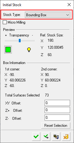
By default, the stock box covers the whole part. The stock size and the XYZ coordinates of the two furthest diagonal points of the stock box are detailed in the Initial Stock dialog (see below).
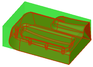
To redefine the stock box, you can either select the entities to be included in the stock by picking By Box or by picking the following entity types: faces, sketches, composites, edges, curves, and points. As you pick individual entities, the bounding box is updated so that it encompasses all the selected entities (see the example of stock creation by bounding box).
Note: The cursor appearance changes as you move over the various entity types defined in the Selection Filter.
The following dialog is used for stock creation by bounding box:
|
|
Pick the surfaces to define the stock. There are several ways to pick surfaces. A popup menu is available for this option. See the dialog Parameter definitions below for more information. Procedures will update the stock immediately after their calculation or only when needed, depending on the relevant setting in the Preferences > NC > General Preferences.
|
Parameters
|
Micro Milling |
When this checkbox is marked
When calculating stock, the tolerance is considered as Micro Milling in either of the following circumstances;
|
||||||||||
|
Transparency |
Control the hide/show state, transparency, and color of the stock. |
||||||||||
|
|
|||||||||||
|
Ref. Stock Size |
The reference stock size based on the entities you have selected. This area shows the size of the stock. The values are for reference only and cannot be changed in this dialog. The Z distance is the difference between the Max. Z and Min. Z values (in the Selected Geometry section of this dialog). |
||||||||||
|
1st corner, 2nd corner |
Based on the entities you have selected, this area shows the coordinates of the diagonal of the bounding box. The values are for reference only and cannot be changed in this dialog. |
||||||||||
|
Total Surfaces Selected |
The total number of surfaces selected to define the stock box. By default, all the surfaces in the part are initially selected to form the stock. |
||||||||||
|
XY Offset Z+ Offset |
Set the respective offset values for the stock. The stock will be offset from the part by this value in the specified direction(s). The offset value can be set separately for X, Y, and Z, with the Z offset having separate controls for the top and bottom to accurately set the location of the extra material. The default value is zero.
|
||||||||||
|
Reset Selection |
Reset: Reset all values and settings to the system defaults. |
||||||||||


The following popup menu options (right mouse button)are available for selecting entities.
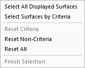
When finished, press one of the approval options.
|
|
OK: Accept the changes, perform the operation, and close the current dialog/task. The stock/part is calculated. |
|
|
Apply: Accept the changes, perform the operation, and keep the current dialog/task open. The stock/part is calculated. |
|
|
Save: Save the settings. Suspend and calculate later. |
|
|
Cancel: Cancel all changes and close the dialog/task without saving the settings. |
|