|
|
Remachine Segments  : Edit Segments

Access: Open this function from one of the following locations:
-
Select NC Process > Model > Remachine Segments from the menu bar.
-
Select Remachine Segments in the Geometry parameters in the parameter tables.
When
the Remachine Segments Table dialog
is displayed, click the Edit Segments
![]() button.
button.
Manage and manipulate Remachine Segments for the Guided Cleanup and Multi Axes Guided Cleanup procedures.
Edit the selected remachine segments. This enables single or multiple segments to be selected and also displays the Edit Segments dialog to perform various operations on the selected segments, such as trim, split, merge and delete segments.
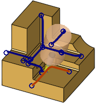
When the Edit Remachine Segments button ![]() is clicked in the Remachine Segments table, the Edit Segments commands are displayed enabling segments (unmachined regions) on the part to be selected and edited.
is clicked in the Remachine Segments table, the Edit Segments commands are displayed enabling segments (unmachined regions) on the part to be selected and edited.
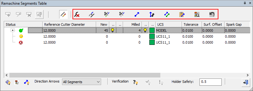
Select the segments and then select the required operation from the Edit Segments dialog.
Edit Operations - these operations are also available from a popup menu (see below). See also the Hidden Segments Note below.
|
|
Delete |
Delete the selected segments. Deleted segments are not machined. |
|||||||||||||||
|
|
Merge |
Merge the selected segments. Merge operations enable cutting the merged segments in one continuous, smooth cut.
|
|||||||||||||||
|
|
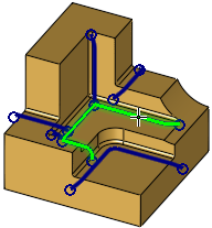
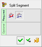
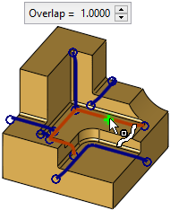
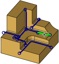
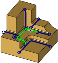
Split |
Split the selected segment. A Feature Guide is displayed. By default, the system selects the splitting point as the point picked on the segment. To change the split point, repick the segment at the required split point. When a point on the segment is picked, an Overlap parameter is displayed. This overlap ensures that the split segments will be machined nearly as smoothly as the original segment (before the split). The result is 2 separate segments with an overlap. The number of segments in the Remachine Segments Table increases by 1.
|
|||||||||||||||
|
|
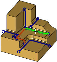
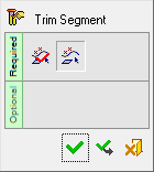
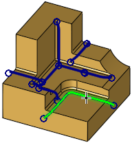
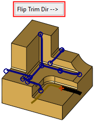
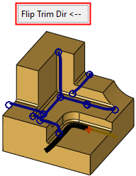
Trim |
Trim the selected segment. A Feature Guide is displayed. The Trim option enables segments to be shortened, avoiding unnecessary machining. By default, the system selects the trim point as the point picked on the segment. To change the trim point, repick the segment at the required trim point. When a point on the segment is picked, one side of the segment is highlighted in black and a Flip Trim Dir. button is displayed. The black highlighted segment indicates the side to be trimmed. Flip the trim direction, as required.
|
|||||||||||||||
|
|
Direction |
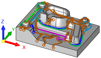
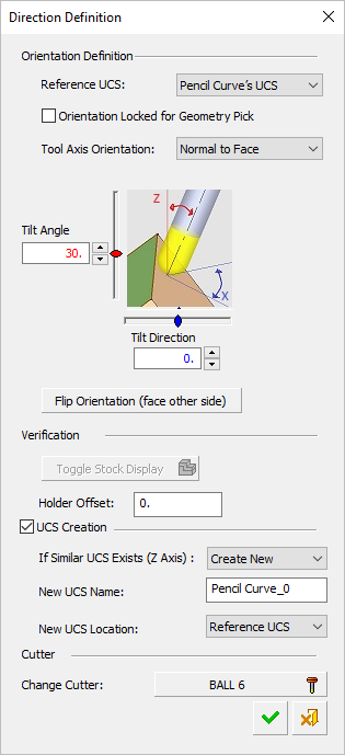
Define a machining direction for the selected segments. The Direction Definition dialog is displayed. If a UCS is created at the bottom of the Direction Definition dialog, it can be used for a 3+2X procedure. If not, the direction will be considered when using a 5X procedure. The default UCS name is Pencil_Curve_## (where '##' is the next consecutive integer), however, the UCS may be renamed.
In the Remachine Segments Table, each direction is defined a color, with the segments in the graphics window displayed in the same color. The default direction colors are defined in the Preferences. The angle between the direction of curves in Remachine segments and the Z of the UCS of the curve, cannot exceed 90°. This is checked for Direction and Paste operations. |
|||||||||||||||
|
|
Auto Directions |
Let the system automatically suggest directions for selected segments. |
|||||||||||||||
|
|
Copy |
Copy the direction of the selected segments to a clipboard. |
|||||||||||||||
|
|
Paste |
Paste the direction stored in the clipboard to the selected segments. This means that the direction that was Copied from a previous segment, is now assigned to the segment selected for the Paste operation. Both segments have the same direction. The angle between the direction of curves in Remachine segments and the Z of the UCS of the curve, cannot exceed 90°. This is checked for Direction and Paste operations. |
|||||||||||||||
|
|
Check |
Check the direction of the selected segments for holder collision. The check considers the Mill Cutter, the defined Holder Safety margin and the set direction. |
|||||||||||||||
|
|
Undo |
Undo each previous operation, starting with the last operation. |
|||||||||||||||


Hidden Segments Note: Once an edit operation is completed, the segments upon which the operation was performed, may be hidden.
This may be because, for example, their orientation has been changed (for an Attach UCS operation), and it is no longer collision free verified. It is now part of the unverified group and can be seen if this group is shown.
Any change in Direction, Mill Cutter, Holder Safety value, as well as any other segment modification, cancels the validation. The relevant segments need to be rechecked.
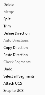
Popup Operations
The edit options described above are also available from a popup menu, when right-clicking in the graphics window when the Edit Segments dialog is displayed. Any additional options appearing in the popup menu are described below.
|
|
|
|