|
|
Remachine Segments 

Access: Open this function from one of the following locations:
-
Select NC Process > Model > Remachine Segments from the menu bar.
-
Select Remachine Segments in the Geometry parameters in the parameter tables.
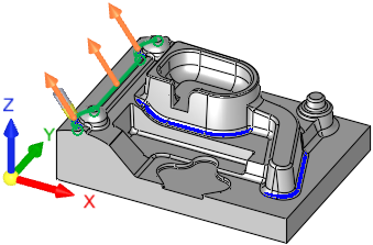
Manage and manipulate Remachine Segments for the Guided Cleanup and Multi Axes Guided Cleanup procedures.
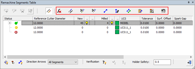
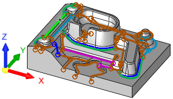
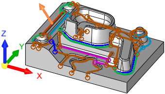
This function finds all unmachined regions (segments) for a previously used reference cutter. All data is displayed in the graphics window and controlled via the Remachine Segments Table.
When the Remachine Segments Table is invoked from the menu toolbar, these segments can be edited as required. They can be deleted, merged, split, trimmed and given a direction based on future machining requirements.
When the Remachine Segments Table is invoked from within a procedure (the NC Parameter table grid > Geometry > Remachine Segments option), editing operations on these segments are not available.
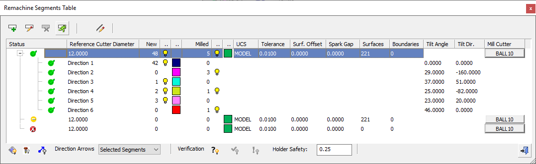
This table is the user interface environment to manage, handle and create the various cleanup segments. The segments are an input for the Guided Cleanup and Multi Axes Guided Cleanup procedures.
|
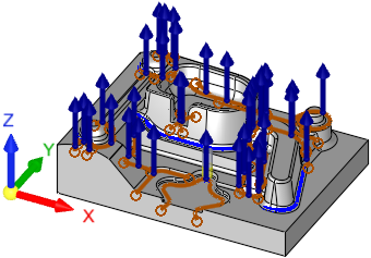
Guided Cleanup: Segments are milled from the Z direction. |
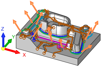
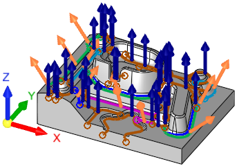
Multi Axis Guided Cleanup: Segments are milled by the vector direction of each curve. |
|
|
|
To better manage the cleanup definition process, you can hide segments already milled and then set a preferred milling direction for each segment, as well as edit segments.
Numerous options are available for controlling the segment definition to obtain the best results and fastest machining time. For example, you can Trim, Split and Delete segments.
The default colors used in this function for the various cleanup segments and milling direction arrows, are defined in a Preference option.
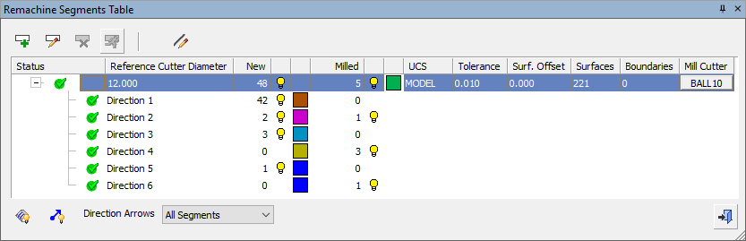
Each main row in the table represents Remachine Segments for a specific (previously used) reference cutter. Reference cutters are defined only by their ball diameter.
Notes:
-
Selecting a main row shows all segments of the row and hides all other main rows.
-
Selecting direction row shows all segments in that direction and hides all others.
-
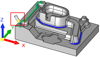
The milling cutter, if defined, is displayed in the relevant direction on the first segment of the direction.
Examples:Examples:The cutter displayed in the relevant direction on the first segment of the direction:
The segment direction arrows:
-
Clicking on a bulb of a direction row does not select it, it just hides or shows the segments on that row.
Table
The table rows are one of the following types:
-
Main Rows:
Each main row in the table represents Remachine Segments for a specific (previously used) reference cutter. A main row contains all the controls listed below for the table columns.
Main Row example:Main Row example:The main row is selected and highlighted:
-
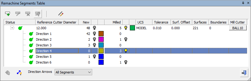
Direction Rows:
Each direction row in the table represents a specific vector direction. Each Pencil curve has a direction vector assigned to it. A direction row contains some of the controls listed below for the table columns.
Direction Row example:Direction Row example:The direction row is selected and highlighted:
The table columns are described below.
|
Status |
Displays the status flags and symbols of toolpaths and procedures. Position the cursor on the status flags icons to display a tooltip explaining the current status flags. |
|
Reference Cutter Diameter |
The diameter of the reference
cutter (the previous cutter)
used to calculate the pencil line segments for the remachine operation.
This parameter is only required
to set the diameter; there is no necessity to select an actual cutter. |
|
New |
The number of new (unmachined) segments. |
|
|
Hide |
|
<color> |
Color for new segments. |
|
Milled |
The number of previously milled segments used for cleanup operations. |
|
|
Hide |
|
<color> |
Color for previously milled segments. |
|
UCS |
Displays the name of the active UCS which represents the direction of the machining calculations. Click the name to select a different UCS from a dropdown list of available options. |
|
Tolerance |
The tolerance for the pencil curve calculation. |
|
Surface Offset |
The surface offset for the cleanup operation. |
|
Spark Gap |
The Spark Gap is the distance between the electrode and the workpiece, where discharges are occurring. This enables Guided Cleanup operations to machine electrodes. |
|
Surfaces |
Displays the number of surfaces selected for the operation. |
|
Boundaries |
Displays the number of boundary contours selected for the operation. The boundaries are used to contain the area within which operations on unmachined regions (segments) are performed. |
|
Tilt Angle |
The Tilt Angle is measured from the Z direction of the Reference UCS. Tilt Angle/Direction Example:Tilt Angle/Direction Example:
|
|
Tilt Direction |
The Tilt Direction is measured around the X direction of the Reference UCS. When the Tilt Direction = 0 the tool tilts towards + X direction of the Reference UCS. Tilt Angle/Direction Example:Tilt Angle/Direction Example:
|
|
Mill Cutter |
Displays the name of the currently used cutter. Click the button to change or edit the cutter; this displays the Cutters and Holders dialog. For this function, only a ball tipped cutter can be selected. |
 /
/
Buttons
The following buttons are in the dialog
Some of these operations are also available from a popup menu (see below).
|
|
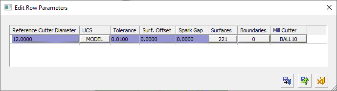
Create a new row at the bottom of the table. This displays the Edit Row Parameters dialog which contains the parameters for calculating the cleanup segments. See Edit Row Parameters.
|
||||||||||
|
|
Edit the selected row in the Remachine Segments Table dialog. This displays the Edit Row Parameters dialog which contains the parameters for calculating the cleanup segments. This button is available when a main row is selected. See Edit Row Parameters.
|
||||||||||
|
|
Edit the selected remachine segments. This enables single or multiple segments to be selected and also displays the Edit Segments dialog to perform various operations on the selected segments, such as trim, split, merge and delete segments. See Edit Segments.
|
||||||||||
|
|
Delete the selected row. This button is available when a main row, that does not have milled segments, is selected. |
||||||||||
|
|
Calculate the selected row. This button is available when a main row, that has not been calculated, is selected. Once a segment row is calculated, you can add |
||||||||||
|
|
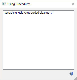
Display the Using Procedures dialog showing the names of the procedures used in the remachine operation.
|
||||||||||
|
|
Hide |
||||||||||
|
Direction Arrows |
For each selected row, define which direction arrows are to be displayed, from the dropdown list of options:
For additional information, see Segment Directions. |
||||||||||
|
Verification |
Hide/Show segments based on criteria:
When all Verification segments are shown, if the main segment row is selected, all segments of this row are shown on screen. Selecting any of the direction rows, hides all other direction segments and displays the cutter in the assigned orientation. |
||||||||||
|
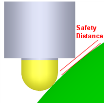
Holder Safety |
Set the safety margin for the holder. The toolpath will not get closer than this value.
|
||||||||||
|
|
Exit: Exit the operation and close the dialog/task. |


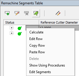
Popup Operations
The button options described above are also available from a popup menu, when right-clicking a main row in the table. Any additional options appearing in the popup menu are described below.
|
|
|
|