|
|
Setup 

Access: Open this function from one of the following locations:
-
Select Tools > Main Tools > Setup from the menu bar.
-
Select Die Design > Tools > Setup from the menu bar.
-
Select Mold Design > Tools > Setup from the menu bar.
-
Select Setup from the Mold Design Guide Toolbar, Parting Guide Toolbar, or one of the various Die Design Guide Toolbars.
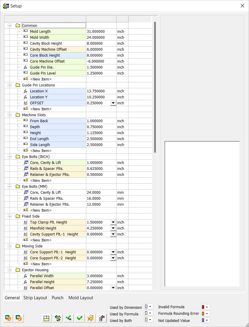
Setup parameters represent geometrical features of the model being designed and also parameters that influence that design. Each parameter can be assigned a value, and the dimension related to this parameter is updated accordingly. These parameters are displayed in the Setup dialog.
|
|
The Setup dialog table displays the entire set of data used in the setup of a Part or Assembly project; these parameters are used in the Part and Assembly environments (assembly includes all assembly projects – plain Assembly, Mold, and Die projects). See Tabs usage for which tabs in the Setup dialog are relevant for each type of project. The table of user-defined parameters is available in the General tab of the Setup dialog. Use this table to predefine various parameters used for creating relations. Setup dialog descriptionThe table of the current assembly can be saved as part of the Assembly Template when using the Save as Template function. Tabs
|
Setup dialog description
This section provides a general description of the Setup dialog that is common to all the projects – Assembly, DieDesign, and MoldDesign. For more on each tab use the links below.
Tabs usage
Some projects types only use the parameters listed in certain tabs in the Setup dialog:
|
Project |
Tabs |
|
Part/Assembly |
|
|
Die |
|
|
Mold |
|
Buttons
The dialog buttons are displayed at the bottom of the Setup dialog. Some are only available for specific tabs and only relevant for parameters in that tab.

|
|
Export the Setup Parameters to Excel. For more, see Setup: Excel integration. |
||||||||
|
|
Read parameters from Excel file into Setup. For more, see Setup: Excel integration. |
||||||||
|
|
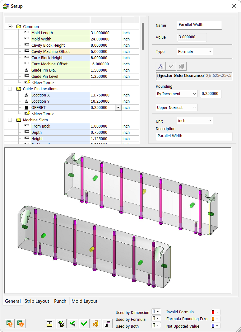
Collapse/Expand – Collapse or expand the parameter picture. This changes the picture from being displayed only in the parameter data area to being spread over the bottom of the dialog. The
|
||||||||
|
|
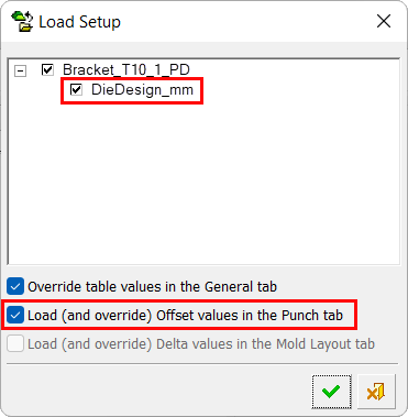
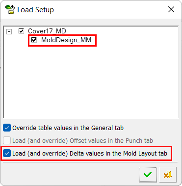
Load Setup - Load setup groups from another file. This is used to select assemblies and parts and then select one or more groups and add them to the current table. When this button is pressed, the Cimatron Explorer is displayed; select the required file. The Load Setup dialog is then displayed showing the a tree of groups; select the required groups. At the bottom of the dialog, parameters options are displayed that enable you to override parameters in the Setup dialog; select the checkboxes as required.
If the following checkboxes are not selected, the current parameters in the Setup dialog are used. If the checkboxes are selected, the relevant parameters are overridden.
|
||||||||
|
|
Apply - Apply changes to the model. |
||||||||
|
|
OK - Accept all changes and close the dialog. |
||||||||
|
|
Cancel - Cancel all changes and close the dialog. |
||||||||
|
|
Collapse/Expand - Hide or show the parameter data area.
|
 /
/ button is displayed when the parameter data area is collapsed (see below).
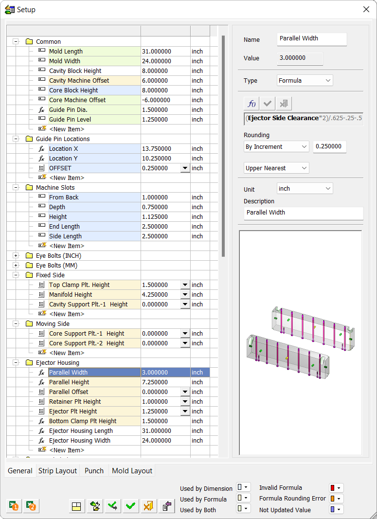


The following button is displayed at the bottom of the parameter values in each tab of the dialog (except the General tab):
|
|
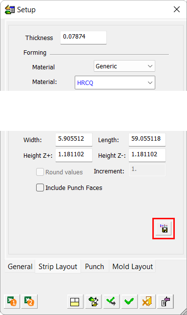
Save as Default - Save all the parameter values in the specific tab as default values in the setup template. In the example below, all the parameter values in the current tab are saved as default values.
|

Markings
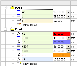
Additional buttons are displayed on the bottom right of the dialog. These buttons are used to mark cells in the table in the General tab. These markings are used to identify where parameters are used or those parameters that have problematic values. The highlight colors can be changed using the dropdown selector.
The following items are highlighted in color in the table:
|
Used by Dimension |
Items that are used in a dimension in the opened file's table. The name cell of the item is marked with a specific color. |
|
Used by Formula |
Items that are used in a formula in the opened file's table. The name cell of the item is marked with a specific color. |
|
Used by Both |
Items that are used by both (by a dimension and by a formula). The name cell of the item is marked with a specific color. |
|
Invalid Formula |
Items that have an invalid formula. The value cell is marked with a specific color. |
|
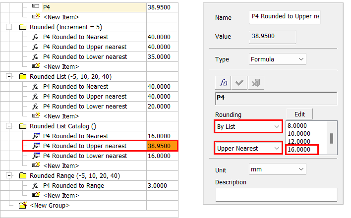
Formula Rounding Error |
Items defined as a Formula where the formula's value is outside the limits set by the rounding rules (By List or By Ranges). The value cell is marked with a specific color. Default color – ORANGE
|
|
Not Updated Value |
Items whose value is not updated. The value cell is marked with a specific color. |
The image below displays example markings.
|
|
|
Format
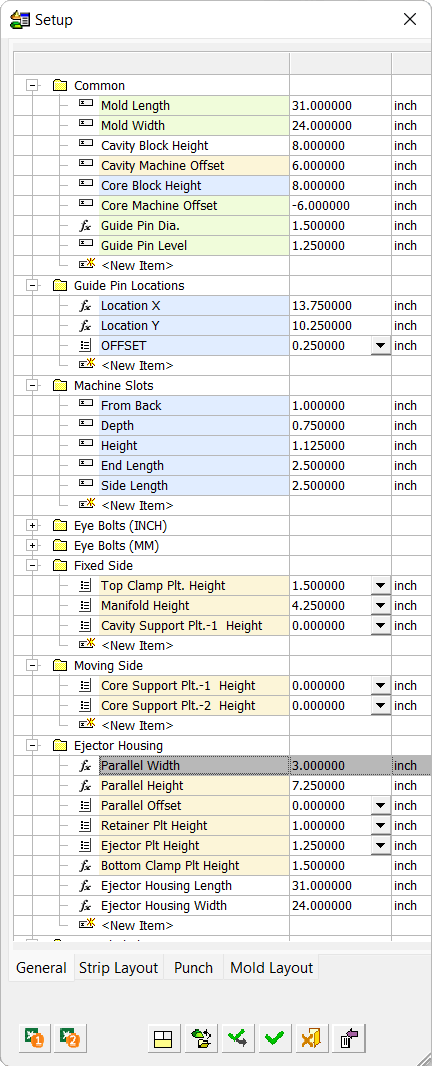
For all projects (Part and Assembly), the General tab displays user-defined parameters. For Mold or Die projects, the Setup dialog holds parameters appropriate to the specific type of project and includes a table of user-defined parameters already formatted for the project (in terms of names, unit dependency, etc.) inside appropriate tabs.
Some of the parameters are derived from the workpiece itself and cannot be changed as long as such a workpiece exists. Other parameters are always input by the user.
A geometric dimension may be related to a setup parameter.
Workpiece
In the Mold and Die projects (irrespective of whether the assembly is stand-alone or placed), Bounding Data area parameters are defined as follows:
-
If a workpiece has been defined, these parameters are derived from the workpiece size and are dimmed (read only). You can round the values by setting a rounding factor.
-
If a workpiece has not been defined (or has been suppressed), these parameters can be edited. If a workpiece is subsequently added (or unsuppressed), then these values are taken from the workpiece and dimmed (as described above).
|