|
|
Simulation Display 
![]()
![]()
Access: Invoke the Machine or Material Removal Simulator and select Simulation Display from the Simulator Guide.
Controls the display of the items that are shown in the graphic window.
The Simulation Display dialog is displayed and differs slightly in the Machine Simulator and the Material Removal Simulator:
|
Machine Simulator Display dialog: |
|
|
There are 3 control zones:
See: |
|
|
Material Removal Simulator Display dialog: |
|
|
|
|
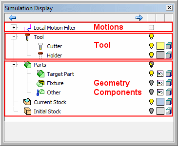
This dialog is similar to that of the Navigator, however, in addition to the hide/show and color buttons, for some items it is possible to control the transparency. The following icons control the display of the various components:
|
|
Hide / Show components, Folder Level Hide / Show / Mixed and Instance - Hide, Show, Mixed. |
|
|
Change the color of a component (original color / user-defined color). A manual change to the color of a motion type will affect all the motions of that type from all procedures. It will be in effect until manually changed or reset. |
|
|
Change the render mode (original render mode/ shade / transparency / wireframe) of a component. |
Usage Example
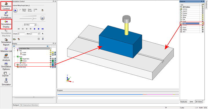
Example of the Display dialog in use.
Note that although all part components were selected to be sent to the simulator separately, none of them is shown when the simulator loads. Only the stock is shown. This is the intended behavior. The part components can be shown at will, using the display dialog control.
Other geometry which exists in the NC file and is not defined as part or stock will be shown in the Simulator window as is. For example, the geometry defined in the set Table.
Note that the Hide/Show set capability in the Simulator is blocked. The reason for that is possible contradiction between sets and the setting in the Simulation Display dialog. To hide this type of 'free' geometry element, use the regular Hide/Show tools - see the example image below.
Simulation Display Dialog Parameters
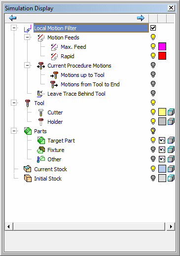
The Simulation Dialog options control the display of the items that are shown in the graphic window. Some of the Local Motion Filter options differ in the Machine Simulator and the Material Removal Simulator. The options that appear only in the Machine Simulator are detailed below, the remaining controls are very similar to those in the Navigator.
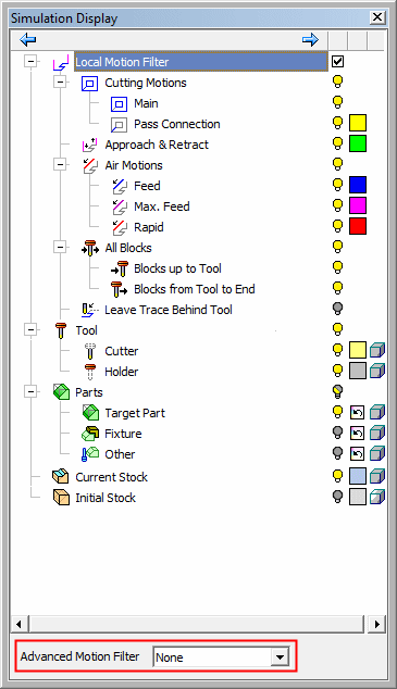
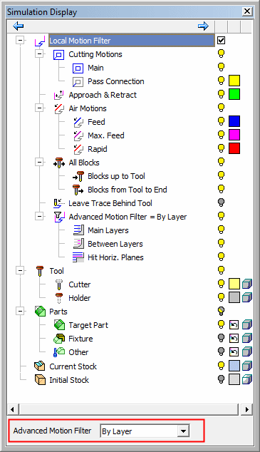
For additional information regarding this dialog, including the Material Removal Simulator options (the Local Motion Filter and Tool branches and the Advanced Motion Filter parameter), see the Navigator.
Note: Tool parameters appear in both the Machine Simulator and the Material Removal Simulator unless specified to the contrary.
|
Motion Feeds |
Display and filter the motions according to their feed type. |
|
Current Procedure Motions |
Display and filter only the motions of the current procedure; the Motions up to the Tool and the Motions from the Tool to the End. |
For additional information regarding this dialog, including the Local Motion Filter and Tool branches and the Advanced Motion Filter parameter, see the Navigator.
The Advanced Motion Filter parameter only appears in the Material Removal Simulator.
|