|
|
Navigator 

Access: Open this function from one of the following locations:
-
Select NC Process > Simulation > Navigator from the menu bar.
-
Select the Navigator button
from the NC Guide Toolbar. -
Right-click on an item in the Process Manager, or anywhere in the graphics window when no procedure is active, and select NC Guide Commands > Navigator from the popup menu.
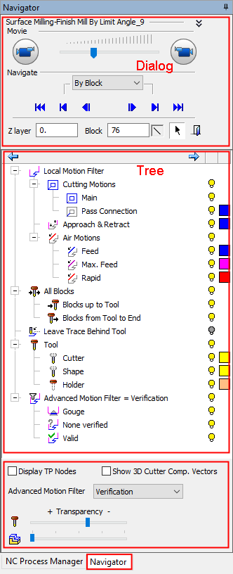
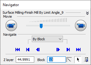
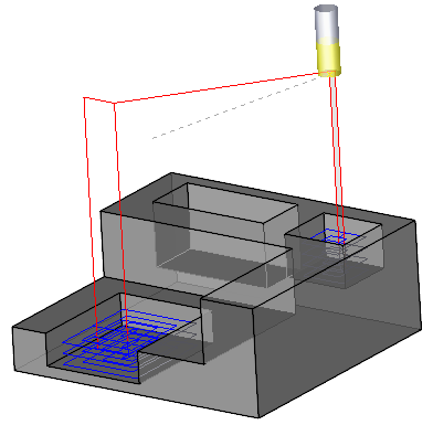
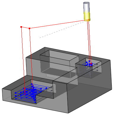
The Navigator is used as a tool to control the display of the toolpath and to analyze it.
The Navigator consists of the dialog, the tree, and the Advanced Motion Filter as shown below.
Note: The Navigator option is dimmed when you are on an empty or a part/stock procedure in the Process Manager.
The Navigator is displayed:
|
|
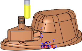
When the Navigator is active (even if you select another tab at the bottom of the dialog), the navigator environment icon is displayed in the right upper corner of the display area. This indicates that you are in the Navigator environment, therefore the Process Manager and other functions are disabled. Once cutter motions have been calculated for a procedure or procedures, the motions can be viewed (per procedure) in the Navigator by one of the following navigation types: The Show Toolpath by dropdown options are displayed at the bottom of the Navigator when the Cutter Compensation is set to Geometry Location (see cutter compensation for explanations):
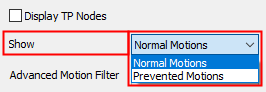
The Show dropdown options are displayed at the bottom of the Navigator if the current procedure has "prevented motions" - motions that were calculated but not machined to avoid holder collision with the part/stock.
|
Note: The Navigator deals with viewing cutter motions created by executed procedures.
-
To edit procedures themselves in order to create new cutter motions (changing geometry, parameters, and so on), see Editing a Procedure.
-
To manually edit cutter motions, see Motion Editor.
-
If you want to modify cutter motion colors, see Colors of Cutter Motions.
Navigator dialog controls
|
<Procedure_Name> |
The name of the current procedure is displayed. |
||||||||||||||||||||||||||
|
|
Minimize The use of these controls is as followsas follows.
|
||||||||||||||||||||||||||
|
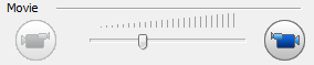
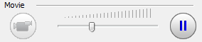
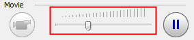
Movie |
Play Click to see Navigator Movie controlscontrols.
These controls enable you to define the following aspects of the movie:
Note: The movie stops running under the following conditions:
|
||||||||||||||||||||||||||
|
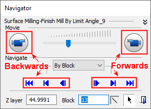
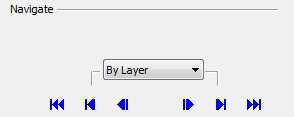
Navigate |
The items displayed in the Navigator are dynamically changed according to the type of Step (group of motions) option selected. The inclusion of a Step type (in the Step dropdown list) is dependent upon its existence in the procedure. For example, if a Finish Limit Angle procedure does not include layered motions (that is, all the machined area is shallow), the By Layer option will not appear in the Step dropdown list.
These optionsoptions are available in the Step (group of motions) dropdown list:
In addition to affecting the motion display, the Step options define the step size for the Forward
If there is only one Navigated Procedure in the file, the |
||||||||||||||||||||||||||
|
Z Layer |
The Z layer of the cutter motion block currently displayed. This displays the current Z layer or enter a value to jump to a specific Z layer. |
||||||||||||||||||||||||||
|
Block |
Number of the cutter motion block currently displayed. This displays
the current motion block or enter a value to jump to a specific motion
block. See the Cutter Compensation: If the Navigator displays the tool in motion inside a compensated region (Cutter Compensation is used), this field is highlighted in orange (as is the Cutter Name field in the Information Bar). |
||||||||||||||||||||||||||
|
|
Icon to show the current segment of the selected Step; linear, circular or spline. |
||||||||||||||||||||||||||
|
|
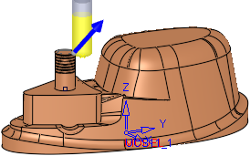
Pick and position the tool on a specific motion block in the display. |
||||||||||||||||||||||||||
|
|
Exit the Navigator. |
||||||||||||||||||||||||||
|
<Tree Area> |
Once cutter motions have been calculated for a procedure or procedures, the motions can be viewed (per procedure) in the Navigator, by one of the following navigation types: |
||||||||||||||||||||||||||
|
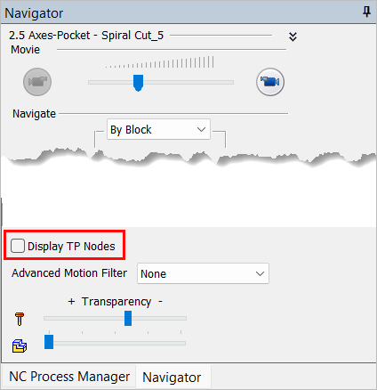
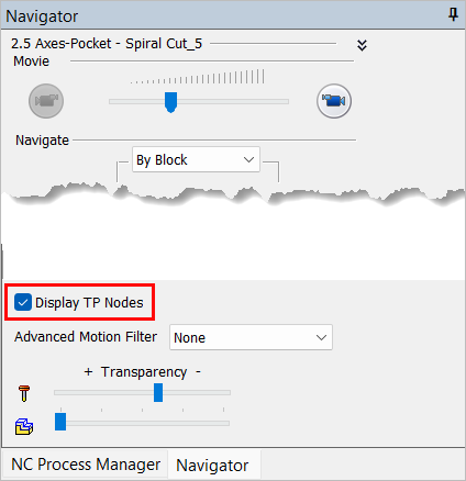
Display TP Nodes |
When this checkbox is marked
Important: This option must first be enabled in Preferences. To enable this option, click Preferences |
||||||||||||||||||||||||||
|
Show 3D Cutter Comp. Vectors |
When this checkbox is marked
|
||||||||||||||||||||||||||
|
Advanced Motion Filter |
The Advanced Motion Filter enables you to view specific motions. The items displayed in the Advanced Motion Filter are dynamically changed according to the active procedures. These optionsoptions are available in the Advanced Motion Filter dropdown list.
|
||||||||||||||||||||||||||
|
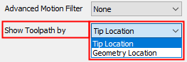
Show Toolpath by |
The Show Toolpath by dropdown options are displayed at the bottom of the Navigator when the Cutter Compensation is set to Geometry Location (see cutter compensation for explanations). Show the toolpath in either Tip Location or Geometry Location mode.
This option is only available when the procedure was executed using the Cutter Compensation: Yes-Geometry Location option. Normally, the Navigator shows the tool motions according to the position of the tool tip. When this option is changed to Geometry Location, the cutting edge of the tool is displayed, NOT the tool tip, or the coordinates that can be seen later in the G-Code after post processing. |
||||||||||||||||||||||||||
|
Transparency |
By using the slider, set the transparency levels for the Cutter & Holder and also the Stock.
|
 and Backward
  Step navigation buttons:


 /
/ 


Notes:
-
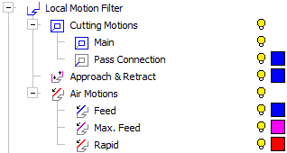
For an explanation of the Local Motion Filter tree, see the Global Filter.
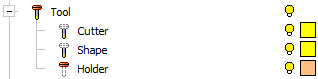
-
For an explanation of the Tool tree, see the Preview.
The Shape is defined in the Machining Param. tab of the Cutters & Holders Dialog, and in the Navigator you can hide/show it.
Navigator display options
The following icons control the display of items in the Navigator:
|
|
Hide / Show specific motions. |
|
|
Change the color of a specific item. |


The default color, line width and line style of the Navigator motions, are defined in Preferences.
|