Simulator Display 
![]()
![]()
Access: Select one of the following methods to access the Simulator:
-
Select NC Process > Simulation > Machining Simulation from the menu bar.
-
Press the
 button from the NC Guide.
 -
Right-click on an item in the Process Manager and select Simulation - Machining from the popup menu.
-
Select the Simulation button in the Job Manager.
The Machining Simulation dialog is displayed. Set the required parameters and press OK ![]() to display the Simulator.
to display the Simulator.
The Simulator display interface is described below.
Display
When the Simulator is invokedinvoked, the Simulator window opens.
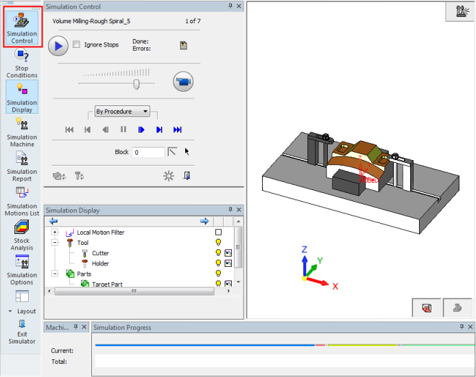
The simulation icon is displayed at the upper right corner of the simulator graphic display:
![]()
Although Machining Simulation is performed on a separate screen, it is easy to use in tandem with the NC environment. You can quickly switch back and forth between these two windows by using the icons in the lower right of the screen. For example, in the event of a simulation issue, this allows for the exact transfer of Z layer or block number information between the two for a thorough investigation of the problem.
The following buttons are displayed at the lower right of the screen:
|
|
|
Switch To CAM Mode (NC programming). |
|
|
Machining Simulation. |
In Machining Simulation mode, the Simulator opens in its own window, as a separate application; similar to having a part document opened in parallel. You can switch between the NC and Simulator application windows through the Windows pulldown menu, or the two buttons in the lower right corner, or by using the CTRL+TAB keys on the keyboard.
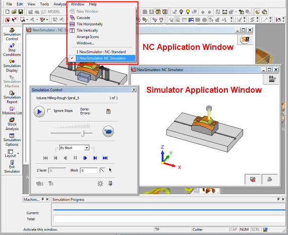
When the Simulator is invoked, a reduced number of icons and pulldown menu commands are available. Only simulation relevant commands and icons are shown.
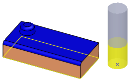
The cutters and holders in the NC and Simulator are displayed in the same colors:
|
NC: |
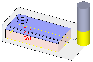
Simulator: |
|
|
|