|
|
Wrap  : Options and Results
Access: Open this function from the following location:
-
Select Faces > Modify Faces > Wrap from the menu bar.
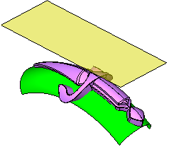
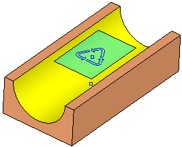
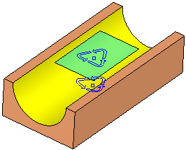
Wrap geometry (faces/wires/curve/points) from an original face onto a target face.
Required Step 1 
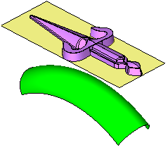
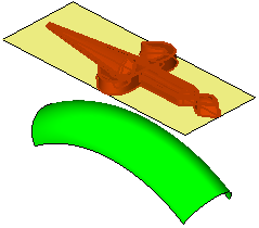
Pick the geometry to be wrapped.
|
|
|
Click <exit><exit> when all objects are selected.
Required Step 2 
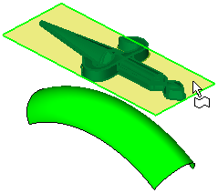
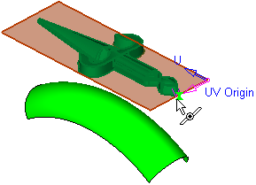
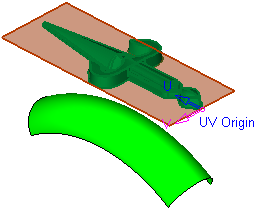
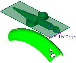
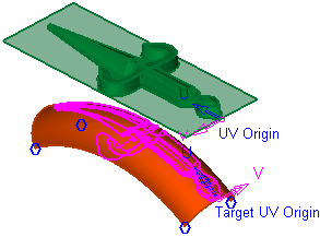
Pick the origin face and reference point. The following face selection options are displayed:

Notes:
-
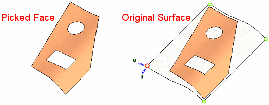
On trimmed faces, the UV origin of the face is the Umin and Vmin value (the base point) of the original surface (before the trim). A marker is placed at each corner of this original surface, enabling you to pick a different corner.
-
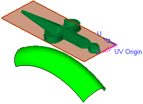
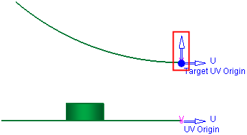
When you subsequently pick a reference point on the selected face, the UV origin is displayed at the picked point.
|
Select |
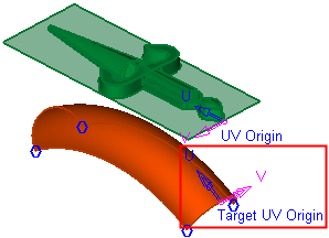
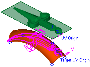
Pick the origin face and reference point. The UV directions (corresponding to the XY directions) are displayed on the selected face and point.
|
||||||||||
|
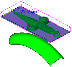
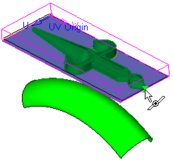
Planar on Active XY Bounding Box |
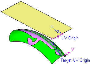
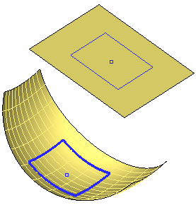
A bonding box of the geometry selected in step 1 is displayed. A temporary planar face is created that reflects the lower face of the bounding box. Pick an origin reference point on the temporary face. The UV directions (corresponding to the XY directions) are displayed on the selected face and point.
|
Press <exit><exit> when all objects are selected.
Required Step 3 
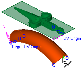
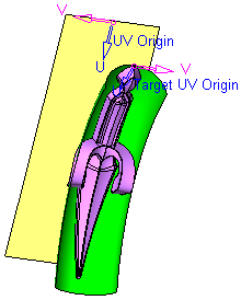
Pick the target face and reference point and set the parameters as required. The following parameters are displayed:
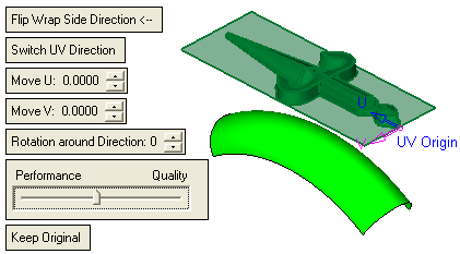
|
Pick the target face. |
Pick the target reference point. |
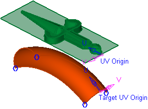
The target UV directions (corresponding to the XY directions) are displayed on the selected face and point. |
|
|
|
|
Set the parameters as required (to save execution time, you can click the Preview button  on the Feature Guide to preview the results before executing the function):
|
Flip Wrap Side Direction |
Decide which side of the target face to display the wrapped entities; flip the side as required.
|
||||||||||
|
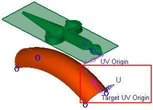
Switch UV Direction |
Switch the target UV directions to produce the required results.
|
||||||||||
|
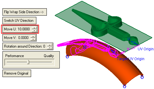
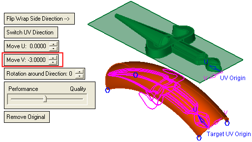
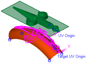
Move U/V |
Move the target reference point along the U and/or V directions.
|
||||||||||
|
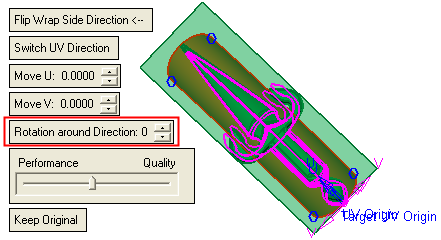
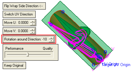
Rotation around Direction |
Rotate the target reference point UV on a plane that is tangent to the surface at the reference point.
|
||||||||||
|
Performance / Quality |
Use the slider to choose between high system performance or high image quality. Depending on the size of the originally selected geometry (the number of geometric entities it contains), the wrap operation may be time-consuming. |
||||||||||
|
Remove Original |
This is a toggle option: Remove Original / Keep Original. Remove or keep the original geometry
|
Optional Step 1 
Set the Wrap parameters. The following parameters are displayed:
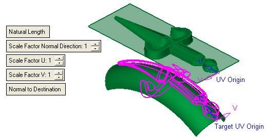
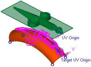
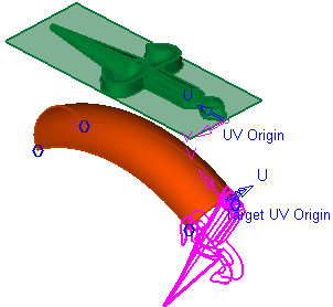
Note: The Preview result (displayed in pink) is shown as a reference for the result of default parameter settings. Compare this result with the results of the parameter settings below.
|
Natural Length |
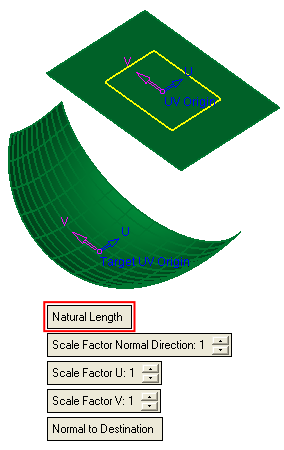
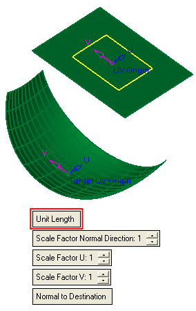
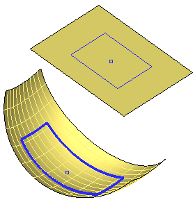
Define how the input geometry (the geometry selected in Required Step 1) is to be mapped to the target face. This is a toggle option: Natural Length / Unit Length.
|
||||||||||||
|
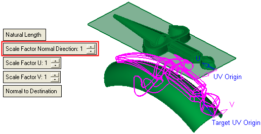
Scale Factor Normal Direction |
Set the scale factor in the direction normal to the destination face.
|
||||||||||||
|
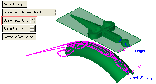
Scale Factor U/V |
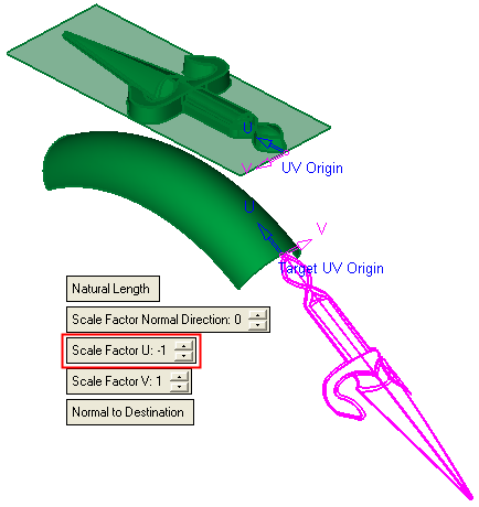
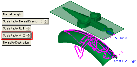
Set the scale factor in the U and/or V directions.
|
||||||||||||
|
Normal to Destination |
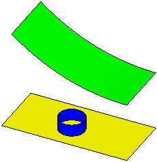
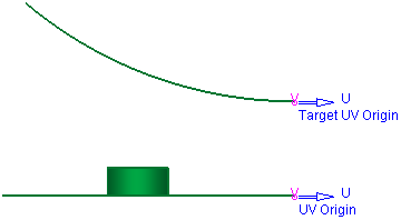
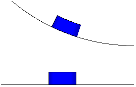
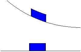
Define how the entities are to be wrapped onto the target face. This is a toggle option: Normal to Destination / By Direction. In the following explanation, the blue cylinder, below, is to be wrapped to the green target face.
|
Click OKOK or ApplyApply in the Feature Guide to complete the function. The geometry (selected in required step 1) is wrapped onto the target face (selected in required step 3).
Examples:Examples:
|
Before Wrap |
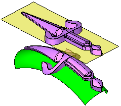
After Wrap |
|
|
|
|
|
|
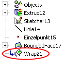
When completed, the Wrap feature will appear in the Feature Tree as follows:
|


