Contour Manager (NC) > By Criteria Selection
![]()
![]()
Access: Open this function from the following location:
Boundary/Contour selection mode:
Either press the button in the Work
Mode Dialog (if you are in Wizard
Mode), or display the Geometry
parameters in the parameter
tables.
button in the Work
Mode Dialog (if you are in Wizard
Mode), or display the Geometry
parameters in the parameter
tables.
The Geometry Table is displayed:
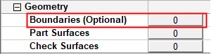
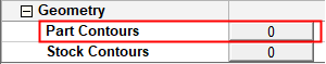
Depending on the current operation, the Boundaries or Contours option is displayed. Press the adjacent button to display the Contour Manager; you are ready to start selecting contours.
See Selecting / Unselecting Geometry.
See the cursor symbols in Cimatron when picking geometry.
Create NC contours by selecting specific criteria upon which the contour creation is based. The By Criteria creation method is very similar to the Multi Contours method. The only difference is the way the input is gathered:
Multi Contours: The input is by manual selection.
By Criteria: The input is automatic according to the criteria definition. From this point on, the mechanism works in exactly the same way.
See Selecting Geometry by Criteria for additional information on the By Criteria method.
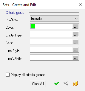
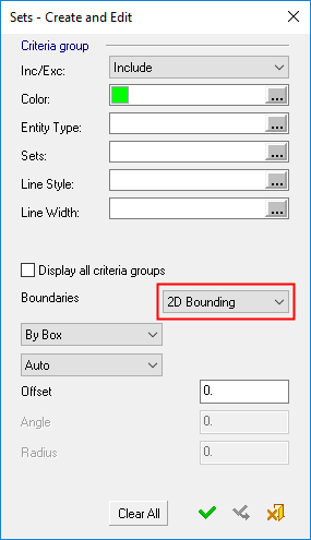
The Criteria selection dialog displayed in the NC environment (the Sets - Create and Edit dialog) is very similar to the dialog displayed in the CAD environment. However, in NC, some parameters are not displayed, while additional parameters may appear in the dialog, depending on the type of geometry being selected.
|
Criteria dialog for selecting 2D Bounding contours: |
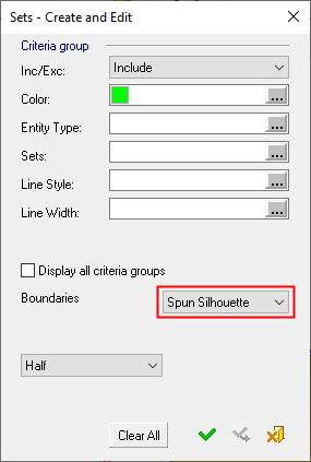
Criteria dialog for selecting Spun Silhouette contours: |
|
|
|
|
|
|
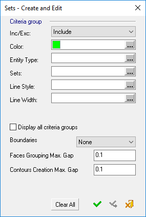
Criteria dialog for selecting Contours: |
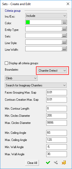
Criteria dialog for selecting Contours for the Chamfer Open Contour and Chamfer Closed Contour procedures: |
|
|
|
|
The By Criteria creation method is very similar to selecting multiple geometric entities manually, the only difference is the way the input is gathered. Using the By Criteria method, the input is automatically selected according to the criteria definition.
The following additional parameters are displayed in the NC "By Criteria" dialog (these are very similar to the same parameters in the Multi Contours Selection):
|
Boundaries (of faces) |
This parameter appears in Contour selection By Criteria. Create contours from faces that meet the criteria, based on one of the following dropdown list of options (this is very similar to the same parameters in the Multi Contours Selection):
A group of faces may have one or more faces. |
||||||||||||||||||||
|
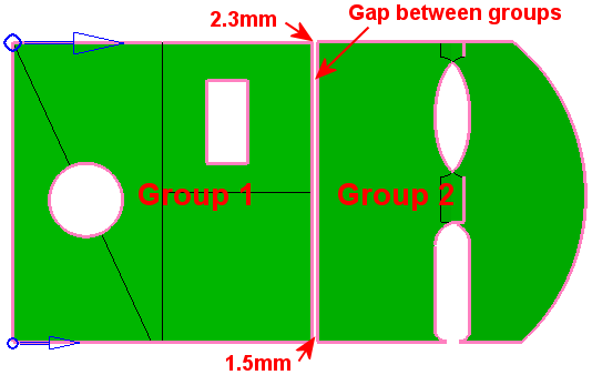
Faces Grouping Max. Gap |
Create Contour geometry based on this Max. Gap value. This maximum gap value is used to analyze the groups of selected faces and create the required geometry. This parameter is used to group faces according to the defined Max. Gap value (the selected faces are grouped considering the gaps between them). In the example below, there are two groups of faces separated by a gap
of 1.5 to 2.3 millimeters. In this example, the Faces
Grouping Max. Gap parameter = 1mm, hence the two groups.
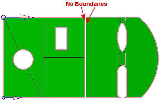
If the Faces
Grouping Max. Gap value is changed to 2.5 (greater than both gap
values), the boundary segments that were before on both sides of the gap
no longer exist. All faces are now grouped in one group.
See the note below regarding this parameter.
|
||||||||||||||||||||
|
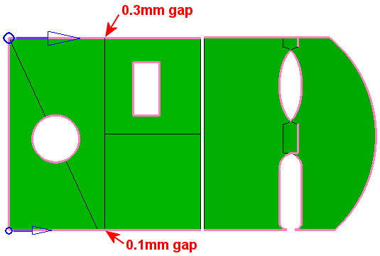
Contours Creation Max. Gap |
Create Contour geometry based on this Max. Gap value. This maximum gap value is used to analyze the edges of the selected faces and create the required geometry. This parameter is used to concatenate the edges to one or more segments, according to the defined Max. Gap value. In the example below, there are two gaps along the contours
(0.1 and 0.3 millimeters wide). In this example, the Contours
Creation Max. Gap parameter = 0.02mm, which is smaller than any
of the gaps.
If the Contours Creation Max. Gap parameter is gradually changed to be greater than any one of the existing gaps (0.2, 0.4, 2 and 2.5), you will notice that the gaps in the contours close one after the other. The contour changes immediately when the changes are done, as the Preview mode is automatic. See the note below regarding this parameter.
|
||||||||||||||||||||
|
Half / Full |
This is a toggle option Half / Full to define the type of Spun silhouette contour to be created from the selected surfaces. The resulting contour is calculated around the Z axis.
This option appears if the Spun Silhouette contour selection method is used. |
Notes:
-
The creation of some contours may be prevented if the Faces Grouping Max. Gap value is greater than the Contours Creation Max. Gap value. In this case, an appropriate warning message is displayed.
-
To hide or show entities that are already participating in NC contours, right-click in the graphics area and select the displayed popup option; Show entities already participating in NC contours or Hide entities already participating in NC contours. See Contour Popup Operations for additional information.
-
The above parameters are saved together with the criteria conditions definition so they are applied each time the contours created by a criteria definition are recalculated.
-
See Creating Sets By Criteria for a description of the remaining parameters of this dialog.