|
|
Add Layout 

Access: Open this function from one of the following locations:
-
Select Parting > Layout Tools > Add Layout from the menu bar.
-
Select Parting Layout Tools > Add Layout from the Mold Design Guide Toolbar or Parting Guide Toolbar.
Create a Layout Part as a skeleton for the multi cavity.
This function is only available if a Layout part was not created in the Mold Project Setup Wizard.
The Layout Part in the Cimatron parting assembly is used to provide center points for locating each molded part. It simplifies mold design because moving a layout point will shift the entire part and runoff associated with it. Several default Layout Parts are supplied with Cimatron, and creating new ones is very easy.
A Layout Part can only contain the following features:
-
A dimensioned sketch of the layout points (the dimensions can be linked to the setup table for ease of access).
-
A Layout UCS on each point (note that a regular UCS will not work).
Adjustment of part position in X or Y is done by changing the sketch point dimensions. Adjustment in Z or part rotation is accomplished by editing the layout UCS (each layout UCS can be adjusted separately when selected).
The Layout Part dialog is displayed.
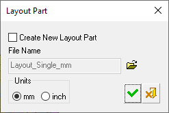
You can either create a new Layout Part or browse using Open File ![]() to add one of your own layout parts or select one of the layout parts supplied by Cimatron. This is a preliminary layout which can be edited in later phases of the mold creation process. The predefined layout parts supplied by Cimatron are placed in the Inch and MM folders located in the following folder:
to add one of your own layout parts or select one of the layout parts supplied by Cimatron. This is a preliminary layout which can be edited in later phases of the mold creation process. The predefined layout parts supplied by Cimatron are placed in the Inch and MM folders located in the following folder:
...\ProgramData\Cimatron\Cimatron\2026.0\Data\dat\ApplicationsData\Layout-parts\
If you create a new layout part, set the units of measurement for the part.
Notes:
-
There will only be one recognized layout part per mold assembly.
-
Any UCS in the Layout part will be considered a Layout UCS. However, note that using a UCS whose Z direction is not aligned with the mold's Z direction may cause undesired results in the QuickSplit simulation of parting surfaces.
Changes in the Tree structure after adding a Layout part
Once a layout part is defined, a Layout part is created in the Assembly Tree and Parting Tree.
The Assembly tree before a layout part is addedThe Assembly tree before a layout part is added
|
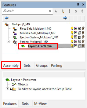
The Assembly Tree, showing the Parting sub-assembly and the Layout part. The latter is created when a Layout part is defined. Note that, when created in the Mold Project Setup Wizard, the Layout part is activated (as shown below). |
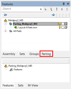
The Parting Tree. The Parting tab allows full control over the parting process, enabling you to activate various parts and control the hide/show status of different Parting sets. |
|
|
|
|