|
|
Parting Menu: Layout Tools
Access: Open this group of functions from one of the following locations:
-
Select Parting > Layout Tools from the menu bar. Select the required function.
-
Select Parting Layout Tools from the Parting Guide Toolbar. Select the required function.
-
Select Parting Layout Tools from the Mold Design Guide Toolbar. Select the required function.
This group of functions is used to add and edit a Layout part. A Layout part is a pattern of coordinate systems used to place the work parts (the next step in the Mold Design Guide Toolbar and Parting Guide Toolbar) within the mold. A layout part can be selected to meet the requirements for either a single or multiple cavity design. Each work part will be placed using a single coordinate system. You can also add a Layout part from the Mold Project Setup Wizard.
Note: You can also add a Layout part from the Mold Project Setup Wizard.
You can either add one of your own layout parts or select one of the predefined layout parts supplied by Cimatron. These predefined parts (inch and mm) are available under the following folder:
...\ProgramData\Cimatron\Cimatron\2026.0\Data\dat\ApplicationsData\Layout-parts\
Notes:
-
There will only be one recognized layout part per mold assembly.
-
Any UCS in the Layout part will be considered a Layout UCS. However, note that using a UCS whose Z direction is not aligned with the mold's Z direction may cause undesired results in the QuickSplit simulation of parting surfaces.
The following functions are available in this group:
|
|
Create a Layout Part as a skeleton for the multi cavity. |
|
|
|
Add an existing parting sub-assembly. |
|
|
|
Create a new parting surface part. |
|
|
|
Create a UCS to be used as a layout UCS and have work parts placed on it. |
|
|
|
Import or add a work part to the assembly and position the work part onto the UCSs in the Layout Part. With this function, you can create a new work part from a master part file or load an existing work part. |
|
|
|
Mark a part as a work part. |
|
|
|
Apply Shrinkage Compensation to compensate for part shrinkage during the mold material cooling process, after removal from the mold and cooling to room temperature. |
|
|
|
Update the size of the bounding box around the work part(s) that are shown in the Setup Mold Layout tab. |
|
|
|
Create the main reference UCS (Work CS) in the work part, defining the position of the work part in the assembly. |
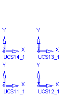
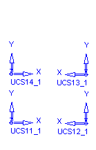
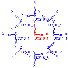
Examples of layout parts:
|
Not Balanced |
Balanced |
Radial |
|
|
|
|
|


