|
|
Add Rule Examples
Access:
Select the Apply Placing Rules and/or
Apply Size Rules checkboxes
in the relevant "Add Component" dialog (see below) when
adding catalog components. The Add
Rules functionality
can also be accessed in the background when other tools are used,
such as the automatic creation of punches.
"Add Component"
dialogs: The
Add Rules (and
Rules Editor) are applicable only when
adding a catalog component (a tool assembly composed of catalog parts)
via designated tools such as
Add
Mold Component, Add
Die Component, Add
Ejectors, Add Ejection
Devices and Add
Cooling Items. In
each of these "Add Component" dialogs, select the appropriate
checkbox to apply the required rule, as shown below:
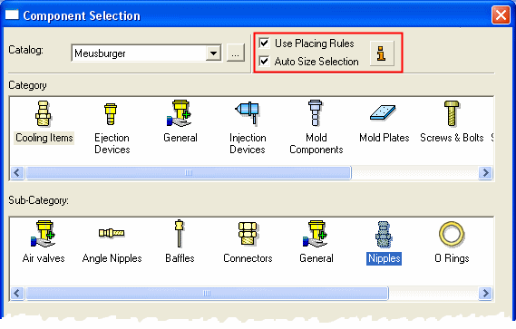
When adding a catalog component, you can automate the process by applying certain rules regarding the location and/or size of the added components. For additional information, see Add Rules and Using Add Rules. Use the Rules Editor to add, delete or edit rules.
The Add Rules (and Rules Editor) are applicable only when adding a catalog component (a tool assembly composed of catalog parts) via designated tools such as Add Mold Component, Add Die Component, Add Ejectors, Add Ejection Devices and Add Cooling Items.
invokeinvoke the Add Rules as necessary.
Examples of Using the Add Rules
The following examples demonstrate the use of the Add Rules when adding catalog components:
- Adding Ejectors
- Adding Spot Cooling Items (such as baffles etc.)
- Adding Punch Screws (may be performed in the background when using "Automatic Punch Creation" etc.)
- Adding Screws while indicating a face
- Adding Punch Keys (may be performed in the background when using "Automatic Punch Creation" etc.)
- Adding Cooling Components
Adding Ejectors
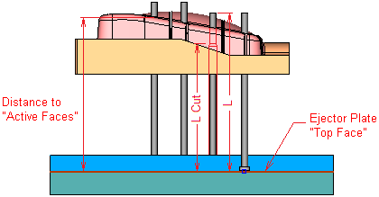
-
Location Rule: - Ejectors are always added on the top face of the ejector plate.
-
Size Rule #1: - The ejector's length "L" is greater than "Distance to Active faces".
-
Size Rule #2: - The ejector's pocket length "L Cut" is smaller or equal to ("Distance to Active Faces" minus 20 mm).
Adding Spot Cooling Items
This includes items such as baffles, etc..
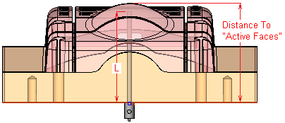
-
Size Rule: - Item length "L" is equal to or smaller than ("Distance to Active Faces" minus 20 mm).
Adding Punch Screws
This may be performed in the background when using "Automatic Punch Creation", etc..
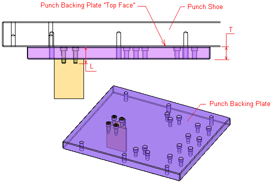
-
Location Rule#1: - Screws are placed on top of "Punch Backing Plate".
-
Location Rule#2: - Screws may be added with respect to the punch face COG (Center of Geometry).
-
Size Rule: – The screw length is greater than or equal to the punch backing plate thickness "T" + Screw Diameter "D".
Adding Screws while Indicating a Face
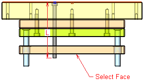
-
Interactive Size Rule: - The length of screw "L" will be greater than the distance between the placement face and the selected face.
Adding Punch Keys
This may be performed in the background when using "Automatic Punch Creation", etc..
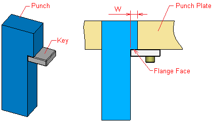
-
Location Rule#1: - The key is placed on "Flange Face".
-
Location Rule #2: - The key is placed at the flange face COG (the key UCS is placed at W/2 distance from its edge).
Adding Cooling Components
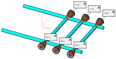
-
Location Rule: – Place on all cone faces with the appropriate attributes (created while the cooling channel is created).
-
Size Rule: – Component diameter "D" is greater than the cooling channel diameter.
Related Topics
|
