|
|
Using Add Rules
Access:
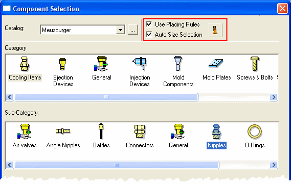
Select the Apply Placing Rules and/or
Apply Size Rules checkboxes
in the relevant "Add Component" dialog (see below) when
adding catalog components. The Add
Rules functionality
can also be accessed in the background when other tools are used,
such as the automatic creation of punches.
"Add Component"
dialogs: The
Add Rules (and
Rules Editor) are applicable only when
adding a catalog component (a tool assembly composed of catalog parts)
via designated tools such as
Add
Mold Component, Add
Die Component, Add
Ejectors, Add Ejection
Devices and Add
Cooling Items. In
each of these "Add Component" dialogs, select the appropriate
checkbox to apply the required rule, as shown below:

When adding a catalog component, you can automate the process by applying certain rules regarding the location and/or size of the added components. For additional information, see Add Rules and Examples of Add Rules. Use the Rules Editor to add, delete or edit rules.
The Add Rules (and Rules Editor) are applicable only when adding a catalog component (a tool assembly composed of catalog parts) via designated tools such as Add Mold Component, Add Die Component, Add Ejectors, Add Ejection Devices and Add Cooling Items.
invokeinvoke the Add Rules as necessary.
The process below describes the difference in the interaction when adding a catalog component using the Add Rules and is relevant to the functions mentioned above (where the Add Rules are applicable).
Required Step 1 
At this stage, w the item is selected, the catalog table is displayed and sizing takes place. Sizing is performed only if the Size Rule is applied (invokedinvoked), otherwise the interaction is as usual (as far as sizing is concerned).
Generally speaking, a size rule will filter the related catalog column per applicable rule. However, some columns may not be fully determined until the parts are actually placed.
Fully Determined Columns
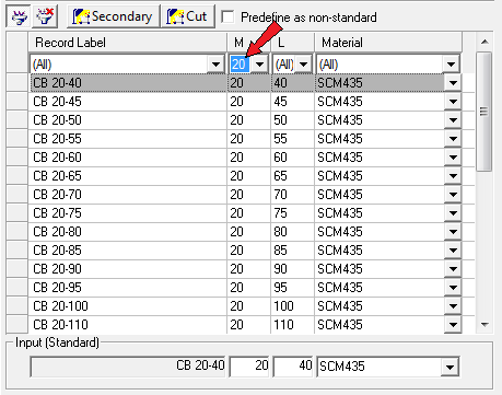
If the size rule is applied, the catalog table is filtered according to whatever size rule is used, for example:

The filtering is removed if the ![]() button is pressed. If the rule involves more than one primary dimension, standard catalog rules apply (columns are filtered from left to right).
button is pressed. If the rule involves more than one primary dimension, standard catalog rules apply (columns are filtered from left to right).
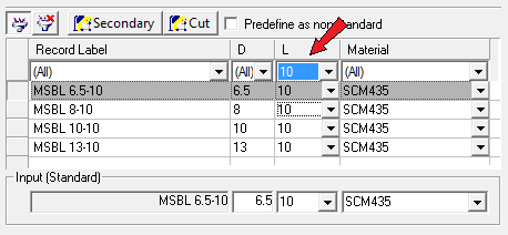
List Values are supported so that the closest value is selected:

Non-Determined Columns
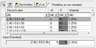
If the size rule involves geometrical parameters yet unknown until the components are placed, the parameter to be determined will be grayed out until proper data is retrieved, for example:

Disabled cells are ignored as far as auto row selection is concerned. Otherwise the usual catalog rules apply (the first row is selected, etc.).
You will not be able to interact with grayed out cells in the input row, otherwise there is no change in the usual table functionality (all options are available, including changing the part into non-standard [predefined or not].).
If you unmark the size rule apply checkbox, standard interaction is returned with no disabled cells.
Required Step 2 
At this stage the location rules are applied and, consequently, the size calculations for the non-determined columns are performed. Location is performed only if the Location Rule is applied (invokedinvoked).
The correct placement method is selected according to whatever is defined in rule (Place by UCS, Place on Face, Place on Cone Face).
|
Place by UCS |
All UCSs conforming with the rule are automatically selected and the components are placed accordingly. |
||||
|
Place on Face |
The face with the proper name/attribute is automatically selected as the placement plane. If more than one suitable face exists, the first found face is selected. The Sketcher is opened, as usual.
|
||||
|
Place on Cone Face |
All cone faces conforming with the rule are automatically selected and the components are placed accordingly. |
Size Calculation
Once the components are placed, the proper size is then calculated as defined in the geometrical parameter size rule (Plane to Attributed/Target Face - Normal Distance, UCS to Face - XYZ Distance, and so on).
If the calculation input has somehow been changed (for example, if components were moved after initially placing them), right-click and select the Recalculate Rules option from the popup menu. This option is only available if components were placed using the size rule Plane to Target Face geometrical parameter.
|
Plane to Target Face |
If required, press <exit><exit> while in the Sketcher, pick the Pick Target Face option from the popup menu and then select the face. The size between the placement face and the selected face can then be calculated. |
|
