|
|
Add Rules

Access:
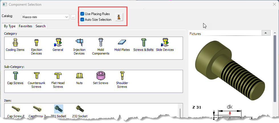
Select the Apply Placing Rules and/or
Apply Size Rules checkboxes
in the relevant "Add Component" dialog (see below) when
adding catalog components. The Add
Rules functionality
can also be accessed in the background when other tools are used,
such as the automatic creation of punches.
"Add Component"
dialogs: The
Add Rules (and
Rules Editor) are applicable only when
adding a catalog component (a tool assembly composed of catalog parts)
via designated tools such as
Add
Mold Component, Add
Die Component, Add
Ejectors, Add Ejection
Devices and Add
Cooling Items. In
each of these "Add Component" dialogs, select the appropriate
checkbox to apply the required rule.
When adding a catalog component, Catalog Rules enable you to automate the process by applying certain rules regarding the location and/or size of the added components. For example, when using Add Mold Component, the system will automatically select the placing and the size of components that contain a suitable rule. This means that if the component you are adding has a mold rule applied to it, part of the Add Mold Component process may be completed automatically.
The Rules (and Rules Editor) are applicable only when adding a catalog component (a tool assembly composed of catalog parts) via designated tools such as Add Mold Component, Add Die Component, Add Ejectors, Add Ejection Devices and Add Cooling Items. In each of these Add Component dialogs, select the appropriate checkbox to apply the required rule, as shown below:
|
|
Use the Rules Editor to add, delete, or edit rules. |
Click the Rule Information buttonRule Information button to display the Rule Information dialog showing all rules associated with the selected component, as shown below. These rules can be edited as required using the Rules Editor.
Rules are divided into two categories, Placing Rules and Size Rules.
Location/Placing Rules:
- Define on which plane the component is located.
- When applied, the rule will automatically select a placement plane, cone face or the UCS where the component is to be placed. In addition, when placed upon a plane, the components can be positioned on predetermined points or the center of geometry of predefined faces.
Size Rules:
- Define the parametric relation between the added part and other components that are already in the assembly.
- The rule defines a parametric relation between one of the new component dimensions, to other component dimensions in the assembly. For example, a rule can define that the length of the "Support Pillars" is equal to the width of the "Riser Plate". When applied, the rule will automatically select parameter values for added components. The parameter value may be linked to a local parameter such as the distance from an active face, or to a global setup parameter.
Notes:
-
The components will NOT be associative to size rules; however, they will stay linked to location rules.
-
Each catalog brand (such as "Hasco", "DME" or "Misumi") has its own set of rules.
-
The rules may be applied on a category, sub-category or a specific item. This means, for example, that all components in a catalog category or all components which are assigned to a sub-category (e.g. the Ejector Pin sub-category) can have the same rule. Individual catalog items can have specific rules assigned to them.
-
Rules per each catalog brand are predefined by the system; however, the Rules Editor is an editing tool that enables you to add new rules, delete rules or modify existing rules.
Related Topics
|