|
|
Assembly Cut > Automatic  : Options and Results
Access: Open this function from one of the following locations:
-
Click the
 button in the toolbar.
 -
Select Assembly > Main Tools > Automatic Cut from the menu bar.
-
Select Die Design > Insert Tools > Automatic Cut from the menu bar.
-
Select Mold Design > Insert > Automatic Cut from the menu bar.
-
Select Insert >Automatic Cut from the Mold Design Guide, Parting Guide or Die Tool Design Guide (DieDesign).
Cut component(s) automatically by component(s) with Cutting Objects according to their cutting rules.
See the differences between the Assembly Cut and the MoldDesign Pocket functions.
In this example, the yellow cap screw is the cutting component:
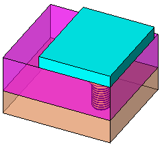
Required Step 1 
- Pick one or more cutting components (must have a cutting object).
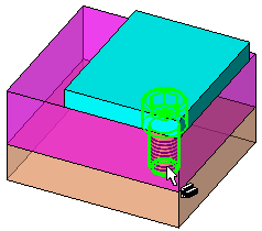
- Pick a plane, one or more faces, or open or closed objects as the cutting tool.
Optional Step 1 
- The Cut Manager is displayed; select the parts to be cut.
- Click OKOK or ApplyApply in the Feature Guide to complete the function.
Results
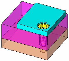
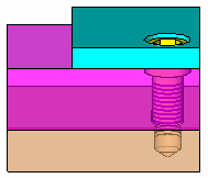
The plates are automatically cut by the yellow cap screw:
Further Example
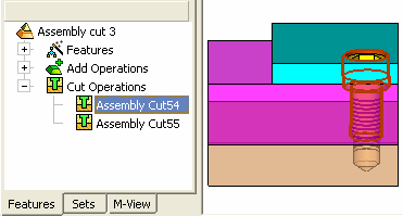
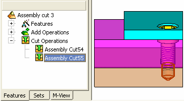
In this example, two Assembly Cut features appear in the Feature Tree. This is because, in the case of Automatic, the assembly cut works according to the cutting rules of the specific part. In this case it is a screw, with a screw cutting rule, which means it has two different cutting objects, each doing its own analysis and cutting the relevant parts according to it. The two operations (features) belong to each one of these cutting objects.
|


