|
|
Auto Alignment  : Options and Results

Access: Open this function from one of the following locations:
Access: Open this function from the following location:
-
Select Die Design > Springback > Auto Alignment from the menu bar.
-
Select Springback > Auto Alignment from the following Die Design Guide: Die Process Design Guide (Forming).
-
Select Solid > Warp > Auto Alignment from the menu bar.
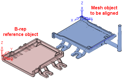
Automatically align two similar objects (B-rep and Mesh) with each other. This function is useful when you import a scan of a manufactured part and compare it with the designed model to look for deviations, or may be used as the first stage in the Warpage Compensation process. The automatic alignment allows to easily match the scanned model to the original model.
For example, to compensate an object for warpage against a mesh object which may be a result from either scanned data or an FEA analysis, the first stage in the warpage compensation process is to align the mesh object to the B-rep object.
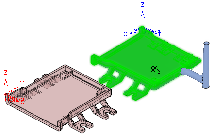
- Pick the object to be aligned and then the reference (target) object (or, in Optional step 1 and 2, pick faces/facets from these objects).
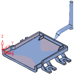
- Align the first object with the second object.
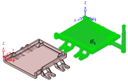
Required Step 1 
-
Pick the object (B-rep or Mesh) to be aligned. The alignment of this object is changed to match that of the reference object selected in stage 2.
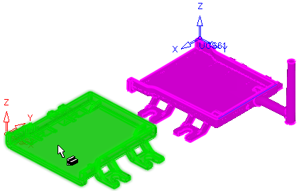
Required Step 2
- Pick the reference (target position) object (B-rep or Mesh). The alignment of this object is fixed. The object selected in stage 1 is aligned to the object selected in stage 2.
Required Step 3 
-
Define the alignment parameters.


The Align Object / Create UCS toggle option is displayed:
Align Object
Align the object selected in stage 1 to the orientation of the object selected in stage 2.
Create UCS
Select a reference UCS from the dropdown list of UCSs on the object to be aligned (selected in stage 1); the default is the active UCS. The reference UCS defines how the objects will be aligned.
The
 button enables you to pick a reference UCS from the object to be aligned (selected in stage 1).
Optional Step 1 
- Pick faces (for B-rep) or facets (for Mesh) from the object selected in stage 1 to be used for the alignment calculation. The selected entities will be used instead of the main object.
In the example below, the Runner in the mesh object is not selected.
Optional Step 2
- Pick faces (for B-rep) or facets (for Mesh) from the object selected in stage 2 to be used for the alignment calculation. The selected entities will be used instead of the main object.
This is similar to the Optional Step 1, but related to the object selected in stage 2 of the function. - Click OKOK
 or ApplyApply
 in the Feature Guide to complete the function.
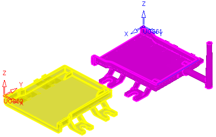
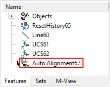
- When completed, the Auto Alignment feature will appear in the Feature Tree
|