|
|
Cap Internal Islands  : Options and Results


Access: Open this function from one of the following locations:
-
Select Faces > Create Faces > Cap Internal Islands from the menu bar.
-
Select Parting > Parting Surface > Cap Internal Islands from the menu bar.
-
Select Parting Surfaces > Cap Internal Islands from either the Mold Design Guide Toolbar or Parting Guide Toolbar.
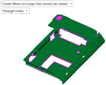
By default, this tool will close open gaps in a solid object, or create internal parting faces in the parting surface part by closing gaps on the work part faces. In addition, you can manually pick other internal loops to enable the function to build capping faces.
|
A solid object example |
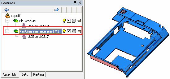
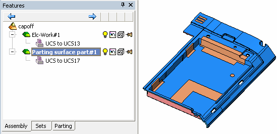
An assembly example |
|
|
|
|
|
|
Note that in the assembly example all the entities belong to the work part. |
||
|
|
Required Step 1 
-
PickPick faces that contain loops to be closed.
-
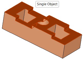
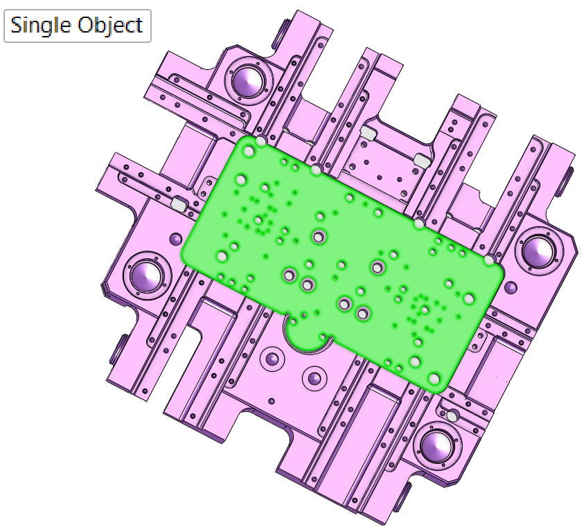
Toggle the Single Object / Multi Objects screen parameter to indicate whether to select the face(s) from a single object or from multiple objects (for multi objects, only faces from a single part can be selected).
|
In the solid object example below, the cyan faces have been selected. See the note below for instructions on selecting by face color. |
In the assembly example, the blue cavity set faces have been selected. See the assembly example note below. |
|
|
|
|

|
Single Object / |
Toggle parameter to select faces from a single object or select faces from multiple objects on a single part.
|
-
ExitExit to proceed to Required Step 2.
-
Solid example
In the solid example, the cyan face set was selected by right-clicking the set and selecting the Select Entities option.
ExampleExample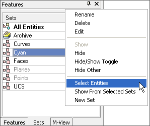
-
Assembly example
In this assembly example, the entire cavity set was selected by right-clicking the set from the Parting tab and selecting the Select Entities option.
ExampleExample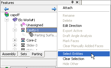
Required Step 2 
-
After exitingexiting Required Step 1, two screen parameters appear in the graphics display area. Set the parameters as required for your work results.
See the Parameters table below for a complete list of parameters available for this function and their definitions. -
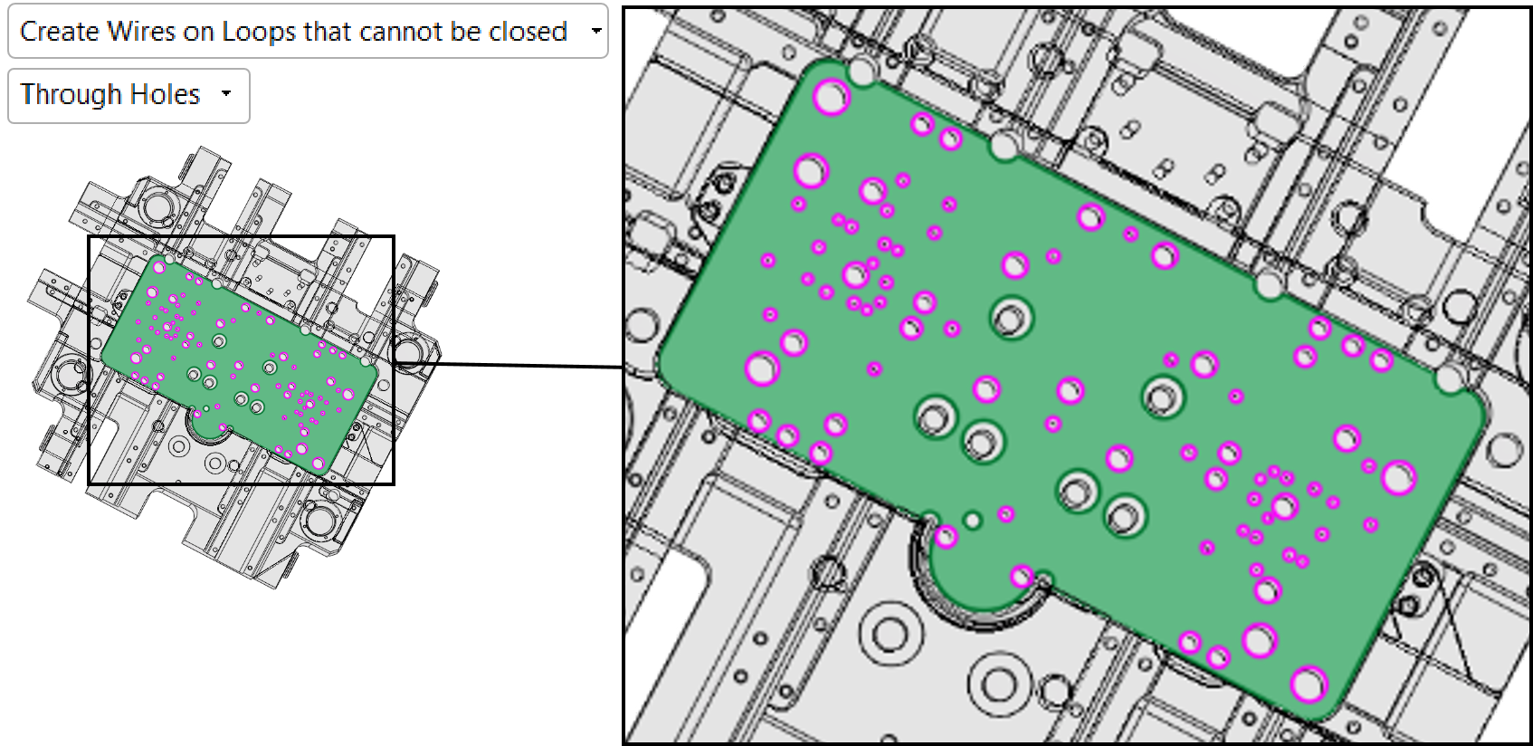
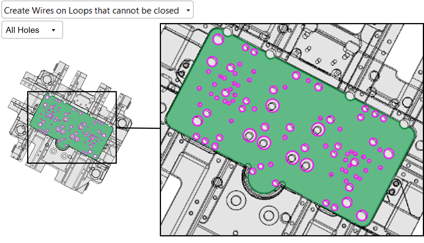
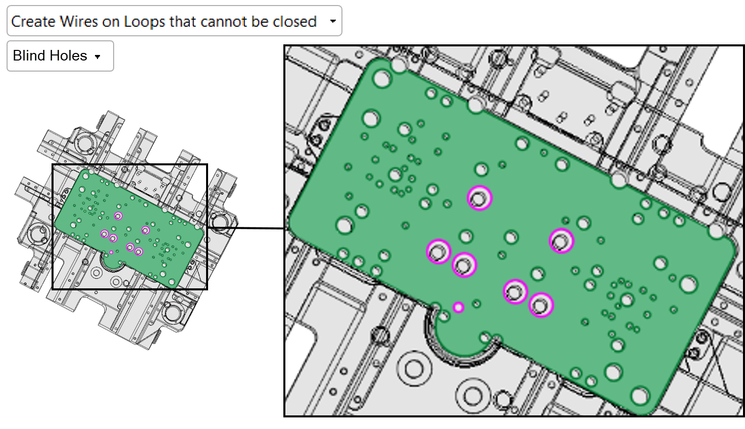
Based on your parameter selections (Through Holes, All Holes, or Blind Holes), Cimatron will automatically select the specified holes. In addition, you can manually pick additional loop(s) to be closed by picking one of the edges.
Note that if you select, User Defined Holes, you will need to pickpick the holes manually.
The object (from which the face(s) was selected in Required Step 1) is displayed in wireframe for clarity. The faces are displayed as selected.
|
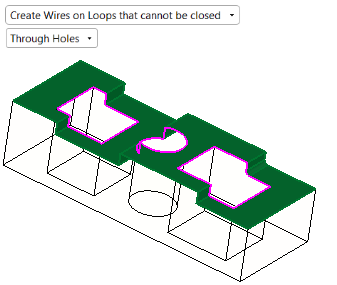
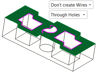
In the solid example below, when selecting the Through Holes toggle parameter in Required Step 2, the system automatically selects all the through holes and highlights them on the selected faces. If required, you can manually pick additional loops to be closed by picking one of the edges of each loop (as shown below) or use By Box to pick multiple loops. |
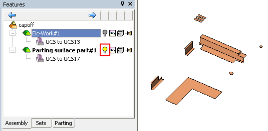
In the assembly example, the inner loops are selected. Pick additional loops or unpick loops as required. |
|
|
|
|
Parameters
|
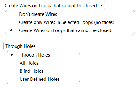
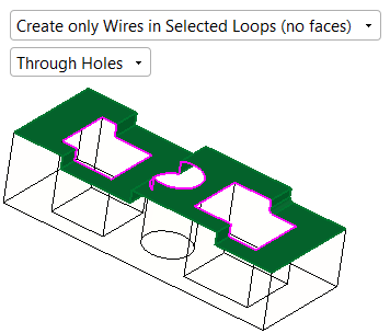
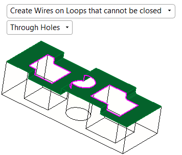
Create Wires on Loops that cannot be closed / Create only Wires in selected loops (no faces) / Do not create Wires |
This screen parameter displays a dropdown list of the following options:
See additional example results below. |
||||||||||||||||||||
|
Through Holes / |
Select an option from the pulldown list to instruct Cimatron to automatically select a particular type of hole or select the holes manually.
|
Example Results
|
Result - solid example |
Result - assembly example |
|
|
|
|
|
|
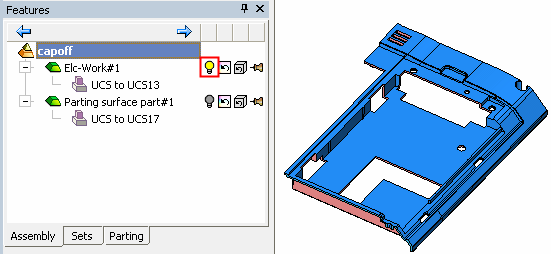
Note that although all the entities belonged to the work part, the internal parting faces were created in the active part. |
||
|
|
Click OKOK![]() or ApplyApply
or ApplyApply![]() in the Feature Guide to complete the function.
in the Feature Guide to complete the function.
When completed, the Cap Islands feature will appear in the Feature Tree.

|