|
|
Circle > Center and Radius 
Access: Open this function from one of the following locations:
-
Select Wireframe > Create Curves > Circle from the menu bar.
-
Select Curves > Circle from the following Die Design Guides: Strip Design.
Create a Circle/Arc by picking its center point and defining its radius.
|
Demo: Press the button below to view
a short movie demonstrating the function:
|
Practice: Press the button below to open Cimatron with a practice ELT file similar to that used to create the movie (if the relevant feature already exists in the ELT file, you can either edit it or delete it and create a new feature). |
|
|
|
Required Step 1 
Select the required parameters and pick the appropriate entities.
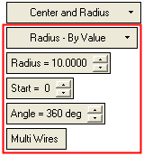
The following parameters are displayed for this Circle function.
|
Radius by Value |
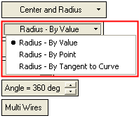
Dropdown list of options to decide how the radius is to be defined. The following options are available under Center and Radius.
Depending on the option selected, the following parameters are displayedthe following parameters are displayed.
|
||||||
|
Radius |
Set the radius of the circle. |
||||||
|
Start |
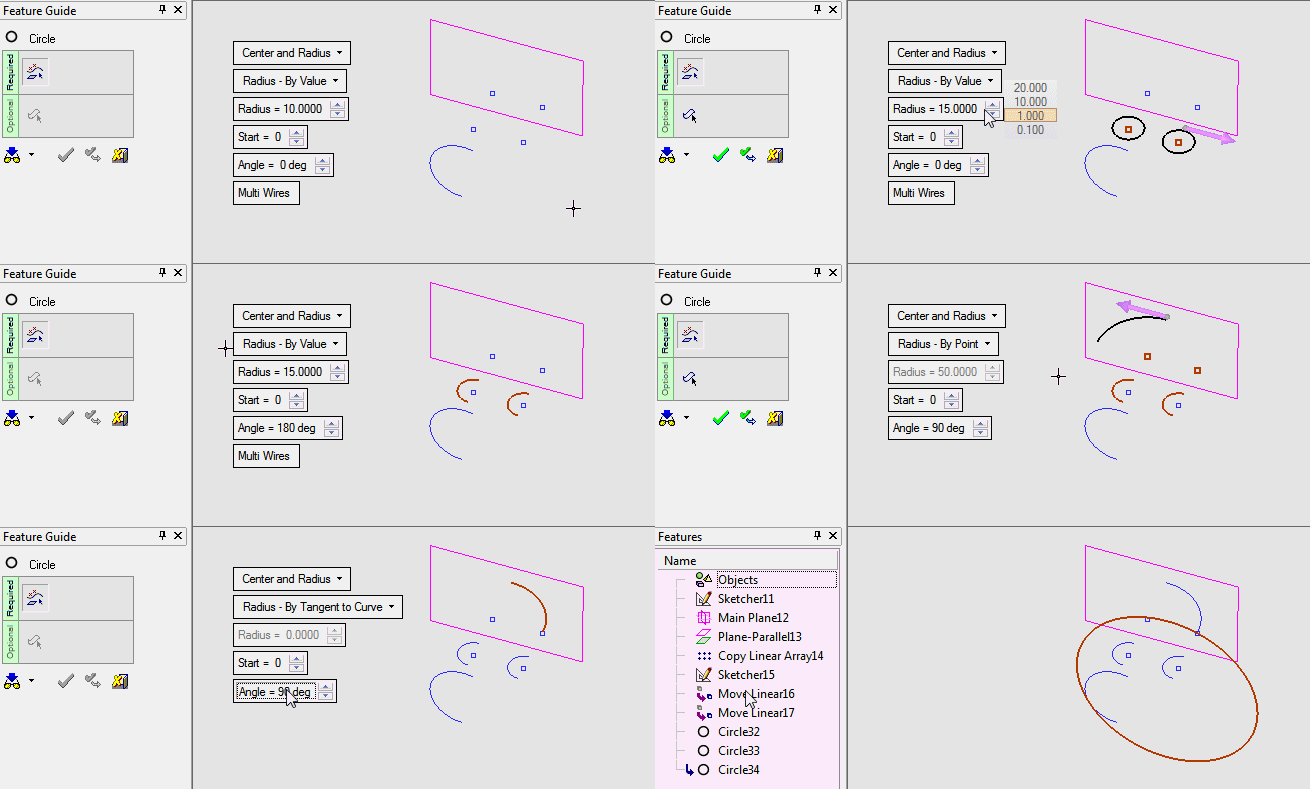
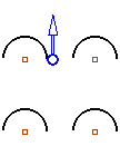
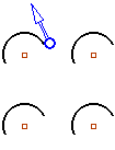
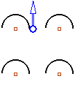
Set the start point of the circle. In the images below, the start point of the circle is at the base of the BLUE directional arrow (this arrow appears if the Angle < 360° and is only displayed here to show the start point location). The images below show multiple arcs.
|
||||||
|
Angle |
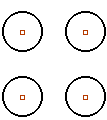
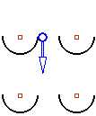
Define the angle of the circle (360 deg) or arc. If the Angle < 360°, a directional arrow is displayed at the Start point of the arc. Flip the direction of the arc by picking the direction arrow. The images below show multiple circles/arcs.
|
||||||
|
Multi Wires / |
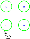
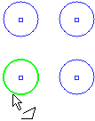
This toggle option defines numerous circles/arcs as a single wire or multiple wires.
|
The subsequent interaction depends on which sub-option is selected:
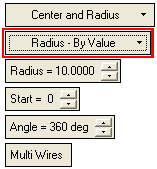
- Radius by ValueRadius by Value
Define the radius by entering a value in the Radius parameter (this is the default option). The following interaction is required:
-
-
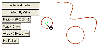
Pick the center point of the circle to be created.
-
-
-
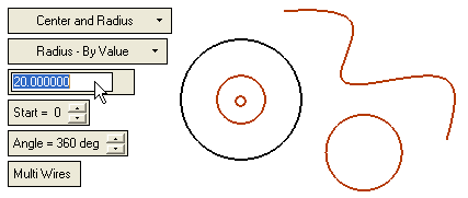
Set the radius, and the other parameters as required.
-
-
-
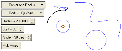
In the case of an Arc, define the Start Point and the Angle.
-
-
-
If necessary, flip the direction of the arc by picking the direction arrow.
-
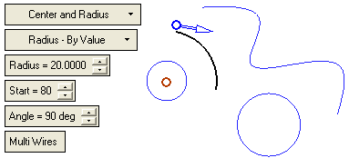
There is only one possible solution.
-
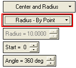
- Radius by PointRadius by Point
Define the radius by picking a point. The following interaction is required:
-
-
Pick the center of the circle.
-
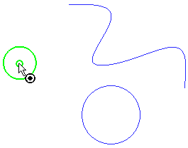
-
-
Pick a point which defines the radius of the circle.
-
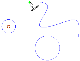
The required circle/arc is displayed.
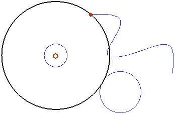
There is only one possible solution.
-
-
Set the other parameters as required.
-
Note: If you change the defined plane in Optional Step 1, the radius will be recalculated according to the projection of the picked point on the new defined plane.
-
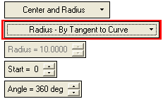
- Radius by Tangent to CurveRadius by Tangent to Curve
Define the radius by picking a curve which will be tangent to the circle. The circle may be created on the extension of the picked curve. The following interaction is required:
-
-
Pick the center of the circle.
-
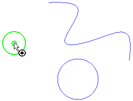
-
-
Pick a curve which will be tangent to the circle. The tangent point defines the radius of the circle.
-
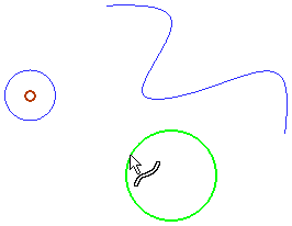
The required circle/arc is displayed.
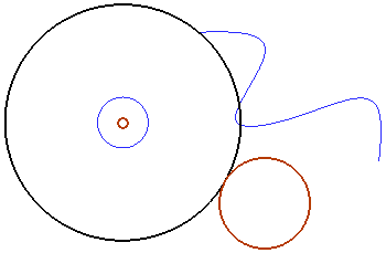
There is only one possible solution.
-
-
Set the other parameters as required.
-
-
Optional Step 1 
Pick a reference plane (If no reference plane is picked, the Circle/Arc is located on the XY plane of the active UCS).
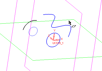
Click OKOK or ApplyApply in the Feature Guide to complete the function.
When completed, the Circle feature will appear in the Feature Tree.

|


