|
|
Conformal Cooling Design  : Options and Results


Access: Open this function from one of the following locations:
-
Select Mold Design > Cooling > Conformal Cooling Design from the menu bar.
-
Select Cooling > Conformal Cooling Design from the Mold Design Guide Toolbar.
Create complex conformal cooling channels.
The system supports mixed/hybrid manufacturing environments with subtractive and additive solutions. A mix of both traditional and conformal cooling capabilities enables efficient design, resulting in shorter injection cycle time and better parts quality due to reduced warpage.
|
|
|
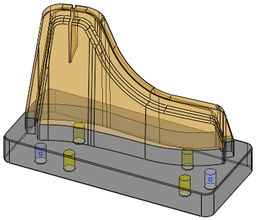
|
Part on which the conformal cooling channels are to be created. |
Conformal cooling channels |
Required Step 1 
-
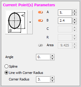
Define the cooling channel. The following parameters are displayed:
The following methods are available for creating the conformal cooling channels:
Dynamically create the spine along which the cooling line body is created. In this mode, you create a polyline (chain of lines) by selecting points.
Example:Example:
For information on editing polylines, see Polyline Edit.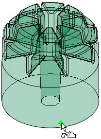
Pick the first point
Pick the next point
A cooling curve is dynamically created between the points
Contours may be selected as input for the channel spine. This means you can design your channel with any wireframe tool (for example, the Automatic Conformal Cooling function) and then use it within the Conformal Cooling design function.
The optimal path of the conformal cooling channel created by the Automatic Conformal Cooling Curve function. This curve is used as input for the Conformal Cooling Design function
The cooling channel created by the Conformal Cooling Design function based on the input - the optimal cooling path curve created by the Automatic Conformal Cooling Curve function
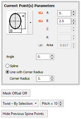
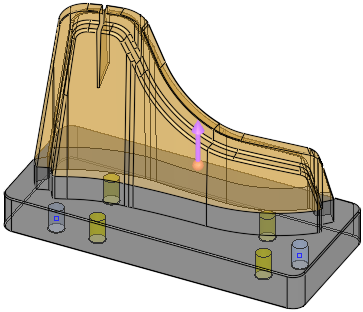
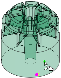
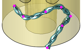
The Current Point(s) Parameters dialog details the parameters of the currently defined point or points. When point(s) are selected, the dialog header text on the Current Point(s) Parameters dialog is displayed in MAGENTA. The points affected by the dialog are also colored MAGENTA; this may refer to the last selected point, the points of a selected spline, or points selected and edited (after clicking the edit button).
This is shown in the images below.
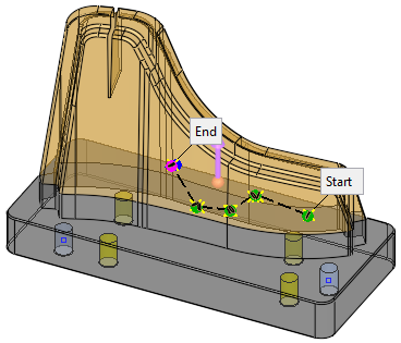
When dynamically creating a spine, the parameters displayed in the dialog refer to the current point displayed in MAGENTA.
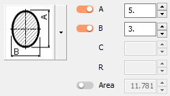
When selecting a predefined curve, the parameters displayed in the dialog refer to the current points displayed in MAGENTA.
When one or more points are selected for editing, the dialog header text on the Current Point(s) Parameters dialog is displayed in the default color set in the Preferences for selected entities. The points affected by the dialog are also displayed in the same color.
When multiple points are selected, the common parameters in the Current Point(s) Parameters dialog are presented and parameters that are not common are displayed empty. You can edit each of these parameters for all selected points. You can also drag multiple points and right-click and delete them.
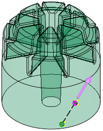
A flip direction arrow allows to change the progression direction of the next point from start to end.
Start and Ends labels are attached to the first and last defined points, respectively. Click one of these labels to switch the progression direction of the conformal cooling curve, so that if you need to add a point at the start of the curve, you simply switch the direction of the start and end points and define the new point.
Sections are automatically oriented in the right direction for printing so that they form a minimal overhang area (if any). You may define a printing direction other than Z to adjust all printing related calculation to the orientation in which the part will be printed. This includes, for example, the orientation of sections and the overhang analysis.
To ensure faster previewing of the channel, by default, the preview of the created channel is not shown. The curve and sections of the created channel are visible at all times. To see the actual channel, click the Preview button. Automatic preview may also be used.
For more, see:
Parameters
Set the shape and dimension of the next created section of the cooling line body.
See Conformal Cooling Cross Section Selection for additional information.
Settings on the dialog are kept when changing to a different shape.
Angle
Rotate the section by the desired angle.
Default = 0.Spline
Select the next curve to be created as a spline.
Line with Corner Radius
Select the next curve to be created as a line. In each corner of the chain of lines dynamically created by selecting points, a radius is defined for the cooling line body.
When this option is selected, the Corner Radius parameter is available. This parameter applies to the corner created after the next pick (between the last created line and the next one). It does not affect previously created corners.
Default = 5mm (0.25 inch).
When set to 0, a sharp corner is created.Mesh Offset Off/
Mesh Offset OnThis is a toggle option Mesh Offset Off / Mesh Offset On that enables you to use a mesh offset of faces and to select points on it.
Mesh Offset Off
A mesh offset of faces is not used.
This is the default option.Mesh Offset On
Use a mesh offset of faces and select points on it. When in this mode, if no faces have been selected, the parameter is displayed in red.
When this option is selected, the following additional parameters are displayed:
Pick the faces to be offset. When in this mode, all screen parameters are hidden and you may select the required faces.
To leave this mode, <exit><exit> to keep the selection, or ESC to lose the selection.Offset
Set the offset of the selected faces.
Default = 3mm (0.125 inch).If at least one face is selected for offset, the following toggle parameter is displayed to hide and show the part geometry for easier selection on offset faces:
Hide Part
Hide all the objects in the part from which the offset faces are selected.
Show Part
Show all the objects in the part from which the offset faces are selected.
Twist - By Selection
Add a section swirl in areas that will enhance turbulence and cooling efficiency. The following dropdown list of options are available:
Twist - By Selection
Twist by Selection allows you to right click any point and define it as the start/end point of the twist. The twist will start from that point until it reaches another point that is marked as ON, and then will stop. This takes into account the direction of the curve, and if the direction is changed – so does the behavior. While in preview mode, the twisted section is colored cyan.
When this option is selected, the Pitch parameter is displayed.
The Start/End Twist option is also available from the popup menu when right-clicking on a selected point.
Twist - Entire Curve
Twisting the Entire Curve marks the entire curve as twisted. The preview of the twisted area of the curve is marked in cyan.
When this option is selected, the Pitch parameter is displayed.Pitch
Set the pitch for the twist operation.
Default = 10 mm or 0.5 inch.
Example:Example:Twist Section OFF:
Twist Section ON
Pitch=5:
No Twist
No area of the curve is twisted.
Hide Overhang/
Show OverhangAn overhang is any part of a structure that has no direct support under it.
This is a toggle option to hide or show any overhang areas that were detected after running an overhang analysis in an optional step of the function.
This toggle option is only displayed upon returning to the Required Step 1 after performing an overhang analysis in an optional step.Hide Previous Spine Points/
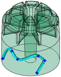
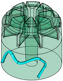
Show Previous Spine PointsThis is a toggle option to hide or show the blue spine points of previous conformal cooling operations.
This toggle option is only displayed if there are previous conformal cooling operations.
Example:Example:Show Previous Spine Points:
Hide Previous Spine Points:
Optional Step 1 
-
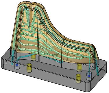
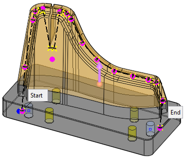
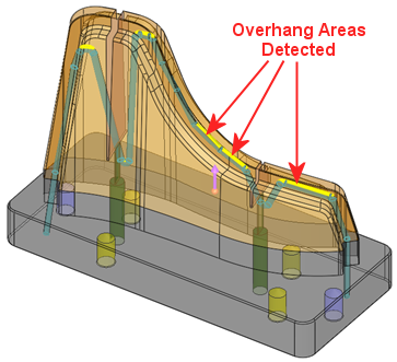
Perform an overhang analysis to ensure no internal areas within the cooling channels will fail during printing.
Based on the overhang angle and minimum allowed width with no support, associated with your printer, material, etc., the system will create a preview of the channel and look for areas where an overhang occurs and supports are required to ensure proper printing. These detected overhang areas are displayed in yellow as shown below. Naturally, supports cannot be created within the cooling channels and if such areas are found, they should be handled by rotating the section or making it narrower at the top.
The following parameters are displayed: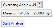
Overhang Angle
An overhang is any part of a structure that has no direct support under it.
The Overhang Angle defines the degree of material overhang from which some support structure should be added to overhanging areas of the model.Defaults are defined by the overhang angle of the selected printer if it exists, or 45° if the printer default is not available.
Minimum Width
The minimum allowed width with no support.
Start Analysis
Start the overhang area analysis, calculating the areas where overhang may occur based on the parameter settings.
This creates a preview of the curve and displays any overhang areas (areas that are beyond the defined Minimum Width and that is somewhat horizontal with an angle lower that the specified Overhang Angle)If overhang areas are detected, they are displayed in yellow and a message is displayed at the bottom of the Current Point(s) Parameters dialog.
Optional Step 2 
-
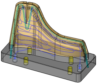
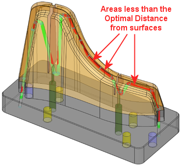
Perform a distance analysis and optimization to identify areas where the channels may be too close to, or too far from, the walls of the insert (based on the defined Optimal Distance value) and adjust them automatically.
The system creates a preview of the channel and finds, for each point, the closest face on the part. Based on an optimal distance, it will create a color map of the cooling channel indicating areas that are too close to, or too far from, the part. Areas less than the optimal distance from surfaces are displayed in red as shown below.
Another option within the same stage allows optimizing the distance by automatically moving the spine points to adjust points that are too close or too far away. Note that not all issues can be fixed automatically and you may need to adjust the spine points manually.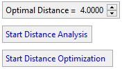
Optimal Distance
Set the optimal distance of the cooling channels from the closest face of the part. This value is used for Distance Analysis and the Distance Optimization operations in this stage of the function.
Start Distance Analysis
When Start Distance Analysis is clicked, it starts calculating the distance between the channel and all surfaces around it in the same part and creates a color map of the cooling channel indicating areas that are too close to, or too far from, the part.
The result of the analysis is a color-coded preview of the channel, based on the defined Optimal Distance, where:
-
Light green = optimal distance.
-
Red = optimal distance/2 or less.
-
Green = optimal distance*1.5 or more.
-
Grey = optimal distance*2 or more.
Hover the cursor over the analysis to display a tooltip showing the distance of the cooling channel to the closest face of the part.
Example:Example: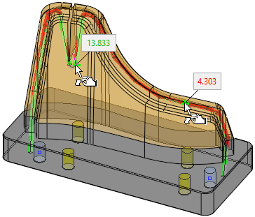
Start Distance Optimization
When Start Distance Optimization is clicked, it starts calculating the distance between the channel and all surfaces around it in the same part and, based on the defined Optimal Distance, adjusts the channel automatically (optimizing the distance by automatically moving the spine points to adjust points that are too close or too far away).
The result of the analysis is as follows:
- When the system detects a section on the line that is less than the optional distance, it moves the curve away from the boundary by 120% of how far it is from the optimum.
- When the system detects a section on the line that is larger than the optional distance by more than 20%, it moves the curve towards the boundary by 80% of how far it is from the optimum.
- A color-coded preview of the channel is displayed. This is the same color-coding as for the Start Distance Analysis.
Hover the cursor over the analysis to display a tooltip showing the distance of the cooling channel to the closest face of the part.
Example:Example: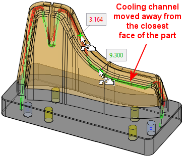
-
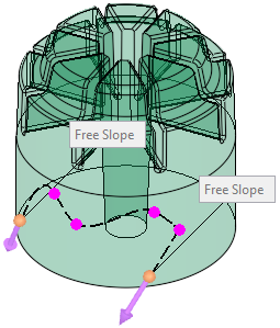
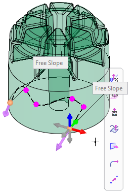
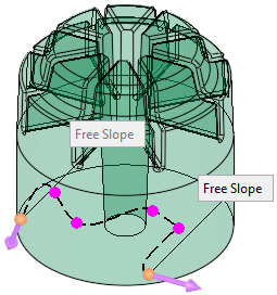
Optional Step 3 
-
Control the slope direction of the curve at the start and end points.
A flip direction arrow allows to change the progression direction of the next point from start to end.The default slope direction.
Click the direction arrow to define a new direction.
Clicking the newly defined direction reverts to the default direction.
- Click OKOK
 or ApplyApply
 in the Feature Guide to complete the function. The system creates the conformal cooling channel. The examples below show the cooling channels created from input from the Automatic Conformal Cooling function.
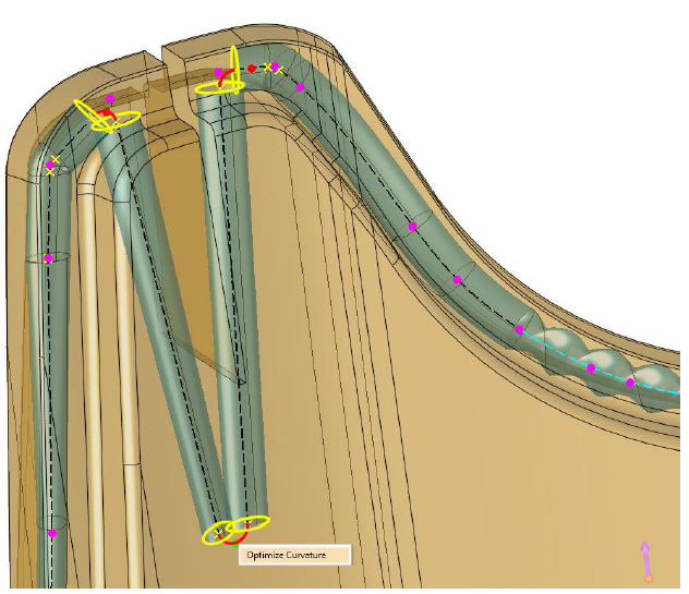
Optimize Curvature: Improving the Channel Path Near Areas Where the Channel Cannot be Created
For areas where the channel cannot be created (these areas are indicated by a red curve and red point in the image below), clickclick on the red curve/point to activate the Optimize Curvature feature. This will shift points before and after the curve, creating the channel path.
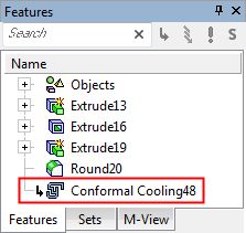
When completed, the Conformal Cooling feature will appear in the Feature Tree as follows:

|