|
|
Analyze Cooling Circuit  : Options and Results


Access: Open this function from one of the following locations:
-
Select Mold Design > Cooling > Analyze Cooling Circuit from the menu bar.
-
Select Cooling > Analyze Cooling Circuit from the Mold Design Guide Toolbar.
Analyze and mark faces belonging to cooling circuitscooling circuits and cooling items.
This function analyzes and marks different cooling circuits in different colors to check their integrity and also mark specific portions of cooling circuits that have designated roles. For example, an analysis recognizes different types of cooling items (plugs, nipples, etc.) and marks them in different colors.
Required Step 1 
Pick the cooling channels to be marked. The following parameters are displayed:
|
|
|
 /
/
Each color adjacent to a face type represents a certain attribute that is given to some of the cylindrical faces. The default color representing each of these entities are defined in the Preferences. If required, click the dropdown arrow to change a color. If a color is changed, all faces marked with the color are also changed to the new color.
A cylindrical face can be marked with one of the following attributes (see the parameter table below for definitions and usage):
-
Running Water
-
Stop Face
-
Inlet/Outlet
-
Baffle
Water collision is marked by the system where there is such an occurrence.
|
This group of parameters applies to all cooling circuits (toggle the parameters expand/collapse button |
|||||
|
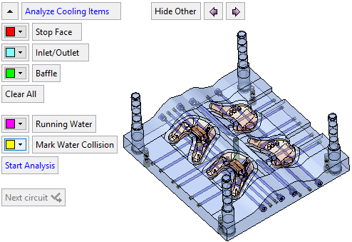
Analyze Cooling Items |
This starts an analysis that looks for and marks (gives attributes and colors) all components which belong to one of the following categories, Stop Face, Inlet/Outlet, and Baffle. The analysis is conducted within the active sub-assembly and below. If a face already has a color and an attribute, it is overridden in the analysis; a face can have only one attribute. For the Stop Face, Inlet/Outlet, and Baffle options, Cylindrical Faces Only / All Faces is a toggle option that enables the support of cooling channels with non-cylindrical faces. Some cooling channels may not be cylindrical, in which case the All Faces option would be used. The default is Cylindrical Faces Only. In this example, the system found the following components and assigned the appropriate attributes and colors. Use the Hide Other button (see below) to show the components found.
|
||||
|
Stop Face |
These are cooling objects that stop the water fluency. Usually they consist of a plug which blocks the water fluency. To manually assign a face as a Stop Face, click on the parameter name and pick the face(s) to be marked as such. When the parameter name is clicked, all other parameters are hidden, and in the display area, all the existing Stop Faces are highlighted.
Press <exit><exit> when finished to redisplay all the parameters. |
||||
|
Inlet/Outlet |
These are faces that contain inlet or outlet items, where water enters or exits the cooling circuit. These include nipples and coupling devices. To manually assign a face as a Inlet/Oulet, click on the parameter name and pick the face(s) to be marked as such. When the parameter name is clicked, all other parameters are hidden, and in the display area, all the existing Inlet/Oulets are highlighted.
Press <exit><exit> when finished to redisplay all the parameters. |
||||
|
Baffle |
These faces contain baffles within the cooling circuit. To manually assign a face as a Baffle, click on the parameter name and pick the face(s) to be marked as such. When the parameter name is clicked, all other parameters are hidden, and in the display area, all the existing Baffles are highlighted.
Press <exit><exit> when finished to redisplay all the parameters. |
||||
|
Clear All |
Remove all attributes (except Running Water) from all the faces. This removes all the following attributes: Stop Face, Inlet/Outlet, and Baffle. |
||||
|
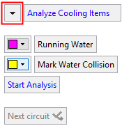
This group of parameters applies only to a selected cooling circuit: |
|||||
|
Running Water |
These faces represent running water. To manually assign a face as a Running Water, click on the parameter name and pick the face(s) to be marked as such. When the parameter name is clicked, all other parameters are hidden, and in the display area, the following parameters are displayed:
New Circuit / Edit Circuit is a toggle option that determines whether you are creating a new cooling circuit or editing an existing one. This parameter is available only when there is one or more cooling circuits already in the assembly, otherwise it is set to New Circuit and grayed out. Cylindrical Faces Only / All Faces is a toggle option that enables the support of cooling channels with non-cylindrical faces. Some cooling channels may not be cylindrical, in which case the All Faces option would be used. The default is Cylindrical Faces Only. Several cooling circuits can exist in each assembly. To distinguish them by color, assign each circuit a different color. Press <exit><exit> when finished to redisplay all the parameters. |
||||
|
Mark Water Collision |
These faces represent water collision. Water collision occurs when there is no defined water flow within the circuit. Mark Water Collision / Don't Mark Water Collision is a toggle option that determines whether to show the water collision areas or not. The default state of this parameter is defined by a checkbox in the Preferences. Below are example results after a Start Analysis operation.
In this example, to prevent the water collision, and to create the desired water circuit (as shown by the arrows below), plugs should be added in the appropriate locations.
Press <exit><exit> when finished to redisplay all the parameters. |
||||
|
Start Analysis |
This button is available when at least one face is marked as Running Water. All faces found by the analysis are given the attribute and color of Running Water. Stop Faces and Inlet/Outlet faces are ignored by this analysis. |
||||
|
Next Circuit |
Apply: Accept the changes, perform the operation, and keep the current dialog/task open. The Next Circuit (Apply) button is available after the Start Analysis button was clicked. This accepts the analysis results for the selected cooling circuit and enables you to select the next cooling circuit for analysis. Each time the Next Circuit (Apply) button is pressed, the color of the Running Water changes. The standard color list is used, starting with the 6th standard color (pink) and then moving forwards one color each time. |
||||
|
This group of parameters enable Hide Other, Previous Hide/Show |
|||||
|
Hide Other |
Hide everything but the selected (in this case, marked) geometry. This shows only those faces that have one of the above attributes (from all the circuits); as shown below:
|
||||
 and
and  functionality, to improve clarity:
Press OK ![]() or Apply
or Apply ![]() in the Feature Guide to complete the function. This saves the color of the faces and assigns them the appropriate attributes. These attributes are considered as "cooling attributes" when performing an analysis in the function Add Cooling Item With Channel.
in the Feature Guide to complete the function. This saves the color of the faces and assigns them the appropriate attributes. These attributes are considered as "cooling attributes" when performing an analysis in the function Add Cooling Item With Channel.
Press Cancel ![]() in the Feature Guide to exit the function without changing the colors and attributes of the faces.
in the Feature Guide to exit the function without changing the colors and attributes of the faces.

|