|
|
Define/Modify Sequence  : Options and Results

Access: Open this function from one of the following locations:
-
Double-click either an Unassigned Group or Sequence Group in the Validate Holes Pane dialog.
-
Right-click an Unassigned Group in the Validate Holes Pane dialog and select Define Sequence from the popup menu.
-
Right-click an Sequence Group in the Validate Holes Pane dialog and select Modify Sequence from the popup menu.
Define/edit a Hole Sequence.
A Hole Sequence is a set of faces describing a hole.
This enables a Sequence to be defined or modified in the CAD environment in a similar way to that performed in the NC Automated Drill environment.
Required Step 1 
Define/modify a sequence. The following parameters are displayed:
|
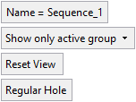
Name = Sequence_<n> |
The default sequence name - where n is an increasing integer. |
||||||||
|
Show only active group |
The following dropdown options are available:
|
||||||||
|
Reset View |
Reset the view to the initial display for this step. If you ZPR away from this view, you can return to the view by clicking the Reset View button. |
||||||||
|
Regular Hole |
This is a toggle option that defines the type of hole:
|
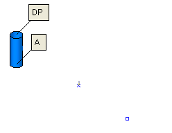
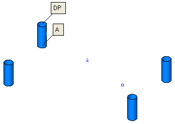
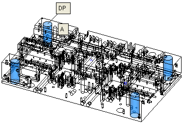
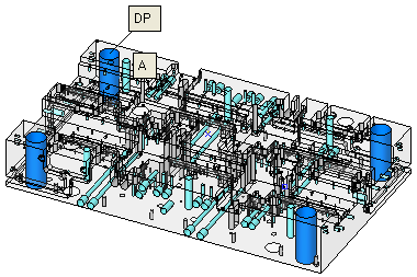
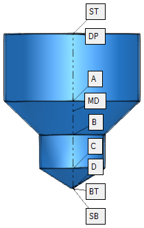
The Geometrical Data table is displayed showing the geometrical data of the selected hole type (anchor point labels are displayed on one of the holes in the hole group):
|
|
|
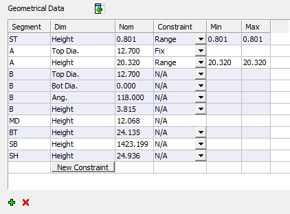
See Geometrical Data Table for a detailed explanation of this dialog.
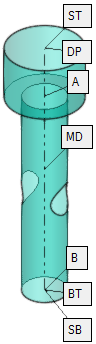
See Hole Anchor Points for a detailed explanation of anchors; a brief description of anchors follows below.
Anchor points are points along the hole axis that are used when defining the parametric drill heights.
Depending on the type of hole, the number of anchor points signifying each segment (A, B, C, D, etc.) may differ. These anchors are named according to their location - A is the closest to DP, then B, etc.
|
|
|
|
|
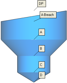
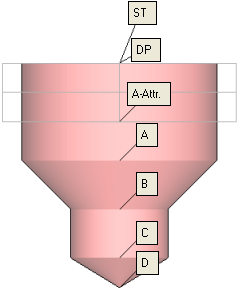
Each anchor point (denoted by a unique letter(s) - unique for each hole) specifies the area from the anchor to the segment above. For example, segment D covers the area from the anchor of segment D up to the anchor of segment C.
Additional anchors define specific points of a hole.
|
ST |
Stock Top: The stock height from the top side. |
|
DP |
Drill Point: The upper point of the geometric hole. |
|
Breach |
Breach: The highest point at which the hole is surrounded by walls. The Breach refers to the top segment of the hole. |
|
MD |
Mid Point: The mid point of length of the hole. This anchor point is used for reference only, as a height for drilling operations, mostly for drilling from both sides. |
|
BT |
Bottom Point: The bottom of a hole. This anchor point enables the same sequence to fit more hole variations from the same hole family. In gun drilling for example, intersections will not require special sequences. |
|
SH |
SH: The total depth of the hole as required; either as (SH=ST-BT) or as (SH=ST-SB). |
|
SB |
Stock Bottom: The stock height from the bottom side. |
See Hole Anchor Points for a detailed explanation of anchors.
Any defined sequence is saved to the Hole and Sequence Library.
The Hole and Sequence Library consists of a master ELT file and a set of approximately 150 sequences suggested for handling the holes in the ELT file.
The default sequence library is located in the following folder:
...\ProgramData\Cimatron\Cimatron\2026.0\Data\Sequences
This library is also used in the NC (Subtractive Manufacturing) environment when Automating Drilling Sequences.
Notes:
-
When invoked from the CAD environment, the sequences are saved without the tool definitions in the Cutter Sequence Data Table.
-
Sequences saved in the CAD environment are also applicable in the NC environment.
|