|
|
Geometrical and Sequence Tables: Cutter Sequence Data

Access: Open this function from one of the following locations:
Select an Automated Drill procedure (from the Process Manager) and choose one of the following:
-
Select NC Utilities > Automated Drill > Define/Modify Sequence from the menu bar.
-
Select the appropriate group (see the note below) and then select NC Utilities > Automated Drill > Define/Modify Sequence from the menu bar.
-
Select the appropriate group (see the note below) and then select Define/Modify Sequence from the Automated Drill Guide.
-
Double-click the appropriate group (see the note below).
-
Right-click the appropriate Unassigned Group in the Group and Sequence Manager and select Define Sequence from the popup menu.
Note: The appropriate group can be either a Sequence Group or Unassigned Group.
Define/edit a Hole Sequence.
A Hole Sequence is a set of faces describing a hole.
This function enables you to pick a group of holes, define a technological process (drilling sequence) to machine the holes and attach the drilling sequence to the group.
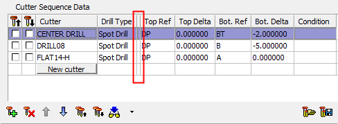
The Cutter Sequence Data table is displayed:
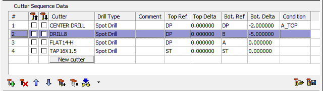
This table displays some of the technological data required to drill the geometry in the Geometrical Data table. The table is initially displayed empty.
Double-click an empty row to display the Cutter Table and select an appropriate cutter, taking into account the data displayed in the Geometrical Data table described above.
Each row in the Cutter Sequence Data table displays the cutter name as retrieved from the cutter library. Click the cutter name to display the Cutter Table and load another cutter in its place.
The following data can be changed directly from the Cutter Sequence Data table (the remaining data can either be filled manually from the Tool Trajectory Parameters table, or from the Cutter Table or from a sequence catalog):
|
# |
Displays the operation sequential number. This enables you to identify an operation. |
|
|
Opposite direction drilling. When the Opposite Direction checkbox is selected in the Automated Drill Tool Trajectory table, an icon is added to the sequence definition in the Cutter Sequence Data table, indicating the opposite direction drilling. |
|
|
Display the cutter (Manual Preview) in its top If the Cutter Sequence Data table contains multiple cutters (more than one row of cutter data), multiple cutters can be displayed at the bottom position. See Using the Cutter Manual Preview. These buttons enable Manual Preview of the cutter: for Auto Preview, see below. |
|
Condition |
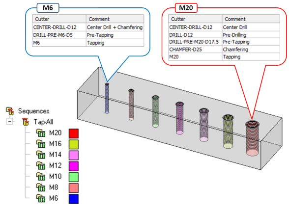
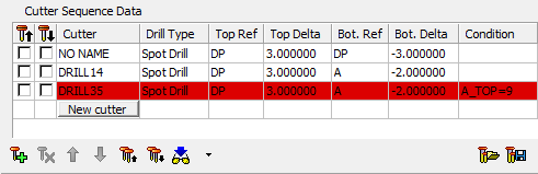
This column is used for setting a condition to a drilling operation. The operation will be executed only if a condition is met (for example, if the hole diameter is larger than 14 mm, a pre-drill will be undertaken with a 10 mm drill). If the condition is not met, the operation is skipped, and the entire line in the table is colored red. See Formula Expressions for additional information regarding the formulas. Condition Usage Example:Condition Usage Example: In the example below, only one sequence was needed to drill these holes with seven different threads – from M6 to M20. Note the different set of tools and operations that were used to drill the M6 and M20 holes.
Double-click a Condition cell to enter a condition. Condition is met:
Condition is not met:
In the Sequences tree, the icon of a sequence that contains a condition is displayed with the letter "C", as shown in the example below.
|
|
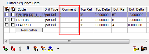
Comment |
A user comment can be added here. This column is, by default, minimized. Comment column hiddenComment column hidden
Comment column shownComment column shown
To enter/change a comment, double-click in the appropriate Comment cell and enter the comment. |
|
New cutter |
Press this button to insert a new row with cutter information. This is the same as using the |


The following table buttons control the contents of the Cutter Sequence Data table:
|
|
Insert a new row. This displays the Cutters and Holders dialog in Select Only Mode. This is the same as pressing the New Cutter button under the Cutter column. |
||||||||||
|
|
Delete the currently highlighted row. |
||||||||||
|
|
Move the currently highlighted row one row up. |
||||||||||
|
|
Move the currently highlighted row one row down. |
||||||||||
|
|
Preview all tools at the top position. All the top position |
||||||||||
|
|
Preview all tools at the bottom position. All the bottom position |
||||||||||
|
|
Display a preview of the active tool. The following Preview options are available in the dropdown list:
When on Auto Preview, if the cursor focus is on the value field of a row in the NC Parameters Table, a preview of the active tool is automatically activated, according to the following rules:
For Manual Preview explanations, see the |
||||||||||
|
|
Load a drilling sequence pre-saved as catalog data. Select the appropriate sequence catalog from the Cimatron Explorer. The data in the table is replaced with the catalog data. See Using the Catalog. |
||||||||||
|
|
Save the current data in the table as a sequence catalog. When this button is pressed, a black frame is displayed in the Graphics Area. This frame represents the capture area of the catalog picture that appears in the Cimatron Explorer in the Preview tab of the Properties pane. This frame enables you to define the content, size (within the black frame) and orientation of the picture. ZPR to obtain the required picture within the frame and then press Apply Capture ExampleCapture Example:
Cimatron Explorer ExampleCimatron Explorer Example:
See Using the Catalog. |
|