|
|
Geometrical and Sequence Tables: Geometrical Data

Access: Open this function from one of the following locations:
Select an Automated Drill procedure (from the Process Manager) and choose one of the following:
-
Select NC Utilities > Automated Drill > Define/Modify Sequence from the menu bar.
-
Select the appropriate group (see the note below) and then select NC Utilities > Automated Drill > Define/Modify Sequence from the menu bar.
-
Select the appropriate group (see the note below) and then select Define/Modify Sequence from the Automated Drill Guide.
-
Double-click the appropriate group (see the note below).
-
Right-click the appropriate Unassigned Group in the Group and Sequence Manager and select Define Sequence from the popup menu.
Note: The appropriate group can be either a Sequence Group or Unassigned Group.
Define/edit a Hole Sequence.
A Hole Sequence is a set of faces describing a hole.
This function enables you to pick a group of holes, define a technological process (drilling sequence) to machine the holes and attach the drilling sequence to the group.
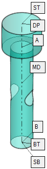
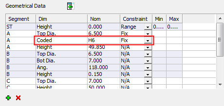
The Geometrical Data table is displayed showing the geometrical data of the selected hole type (anchor point labels are displayed on one of the holes in the hole group):
|
|
|
|
Toggle the Expand |
|
|
|
|
 /
/  button to display the full table or a minimized table. Note that the full table also displays New Constraints.
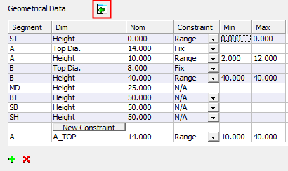
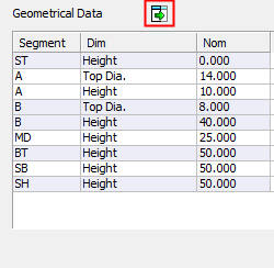
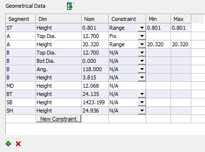
Table headers:
|
Segment |
The name of the hole segment anchor being measured. |
||||||||
|
Dimension |
The type of dimension being measured in each segment. Depending on the shape of the segment, this could be Diameter, Height, Bottom Diameter, Angle, etc. The following Hole attributes can also be used: Notes:
|
||||||||
|
Nominal |
The nominal value of the dimension. This data is calculated when the system performs the geometrical analysis on the group of holes. This data is not editable. In the picture and tables above, for example:
If the Dim column contains a hole attribute (Coded, Thread, etc.), the Nominal column may contain attribute values, such as "H6", "M10", etc.
|
||||||||
|
Constraint |
A dropdown list detailing how the Nominal value is used when creating the sequence. The following options are available:
|
||||||||
|
Min./Max. |
These columns are only available when Range is defined in the Usage column. These parameters define the minimum and maximum values of the range of dimensions for use when scanning for an appropriate sequence. The default values are either set at the nominal value or are taken from the catalog. These values can be changed as requiredchanged as required. To change the Min./Max. values, double-click on the relevant value and enter a new value.
|
||||||||
|
New Constraint |
Press this button to insert a new constraint in the geometrical data of the selected hole. A constraint can be defined as a formula; for example, you can define that A-Height + B-Height should be in a specified range. See Formula Expressions for additional information regarding the formulas. When this button is pressed, a new row is displayed with default data, with the first two columns empty. Enter the constraint in the second column. The first column is read only and contains the segment name used in the formula. When a geometrical variable is entered in the constraint cell (eg. A_TOP), the system automatically adds the segment name part of the constraint (eg. A), into the Segment Column. See Formula Expressions for the types of geometrical variable that can be used in formulas. |
The following table buttons enable you to add or remove constraints:
|
|
Add a new constraint. This is the same as pressing the New Constraint button. |
|
|
Remove a highlighted constraint. This button only deletes a relation constraint. |


|