|
|
Die Skin  : Options and Results
Access: Open this function from one of the following locations:
-
Select Die Design > Blanking Tools > Die Skin from the menu bar.
-
Select Die Skin from the following Die Design Guide: Die Process Design Guide (Forming).
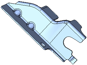
Create a skin (with no thickness) from an object. This enables clear and easy analysis of operations in the system.
An example is shown below:
|
Solid body before creating the skin |
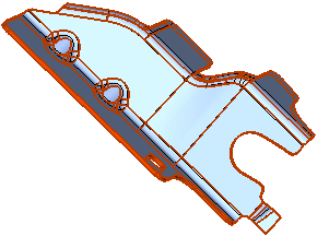
The skin result. |
|
|
|
When selecting a face (or faces), all the smooth faces are automatically selected, provided the smooth selection option is turned on. It includes the following:
-
Enables selecting one or more faces.
-
Enables selecting faces from different objects.
-
Enables performing more than one Die Skin operation on the same part.
Required Step 1 
-
Pick the face(s) of the solid object from which to create the die skin.
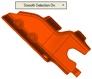
The following parameters are displayed in a dropdown list:Smooth Selection On
Automatically select all smooth faces.
Examples:Examples:Pick a face:
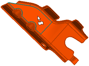
All the smooth faces are automatically selected.
The skin result.
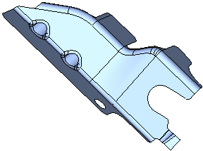
Smooth Selection Off
Pick individual faces.
Examples:Examples:Pick a face:

The picked face is selected.
The skin result.
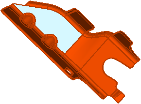
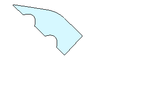
Overcome Sharp Corners
This option enables you to select all faces if only sharp edges exist in the solid object (bend radii are not defined). Additional parameters are displayed that enable you to create a die skin from objects that either have a constant or variable thickness. Examples of these types of objects are
Example of an object with sharp corners and constant thickness:
Example of an object with sharp corners and variable thickness:
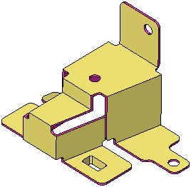
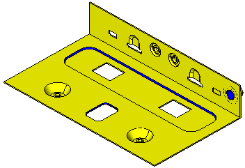
Additional parameters are displayed when using this option.
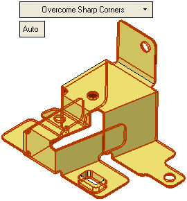
Examples:Examples:The toggle options Auto / Define Thickness are displayed:
Auto
The system automatically calculates the thickness of the part. This option is for parts with a constant thickness (a skin that was shelled).
When a face is picked, the sharp corners are overcome and all the faces are selected.
The skin result.
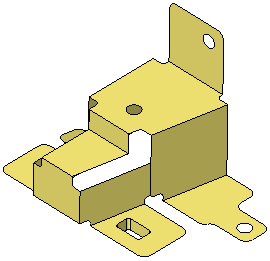
Define Thickness
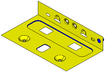
Define the thickness of the part. This option is for a more complex part (mainly in electronic equipment parts) when the thickness is not constant (in some areas the "global" thickness is changed). In this case, you need to define a range of thickness levels, so that all the thickness values in the object are included in the Die Skin operation.
The following parameters are displayed:
From Thickness
Set the lower value of the thickness range.
To Thickness
Set the higher value of the thickness range.
The default thickness for this operation is either taken from the Die Setup dialog (if it has been defined), or from the thickness range.
When a face is picked, the sharp corners are overcome and all the faces are selected.
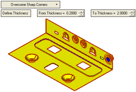
The skin result.
-
Click OKOK or ApplyApply in the Feature Guide to complete the function.

When completed, the Die Skin feature will appear in the Feature Tree

|


