|
|
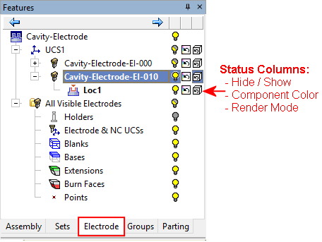
Electrode Tree Structure
The structure of the Electrode Tree displays the electrode hierarchy (Component > UCS > Electrode > Location), enables full control over the entities and their display, and enables numerous operations to be performed from the tree.
See also
|
|
All Visible Electrodes:
|
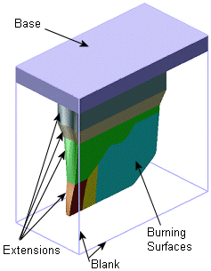
Example electrode:Example electrode:
Electrode Tree UCS
When hovering over a UCS in the Electrode Tree, a tooltip is displayed showing the original name of the UCS and also its component name. This is the original UCS you selected when creating the reference UCS.
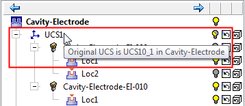
When the UCS in the tree is clicked, it is highlighted in the graphics area.
Electrode Tree Hide/Show
The visibility (hide/show) status can be set for electrode components for all the electrodes in the tree - see the electrode tree example above.
For each electrode location the following characteristics can be set: visibility (hide/show) status, color and render mode (shade / transparency / wireframe) - see the electrode tree example above.
Note: Regarding the visibility (hide/show) status of electrode components, note that hidden items will not appear in the electrode drawings, so before creating electrode drawings, it is recommended to show all items that you wish to see in those drawings.
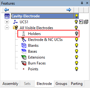
If an electrode component does not exist, the relevant component in the tree is grayed out, as shown below (the Holders component).
|