|
|
Table of Holes: Creating the Table 

Access: Open this function from one of the following locations:
-
Click the
button in the toolbar. -
Select Symbols > Tables > Table of Holes from the menu bar.
Create a Table of Holes (TOH). A Table of Holes displays a list and description of each hole in a specific view of a part. These holes can either be entities that are defined as holes, or points and circles created in the Sketcher.
Create a table of holes
-
InvokeInvoke the Table of Holes function.
The Table of Holes dialog is displayed:
The buttons in the Data area of this dialog make up the steps required to create a table of holes. The buttons are displayed when they are available for selection (usually when you have completed the previous step). When invoking this function using the route described in the AccessAccess button above, the system presumes that you wish to create a new table of holes and the first button (Pick a View) is already in "selected" mode. When a button is selected (or pressed), it has a white background.
The following buttons (steps) are available:

Pick a View: Pick a reference view (containing the holes) from which the table of holes is to be created.

Define the Origin Location: Select the origin UCS for the table of holes.

Sketch Holes Selection: If required, click this button to define new holes directly in the TOH by using Sketcher entities (points and/or circles) in the active view (the view from which the TOH was created). These new holes do not need to be created in the model and the model is not updated (the new hole(s) exist only in the TOH). For additional information, see Defining Sketch Holes in the TOH.

Set the Table Location: Set the table location to define the origin location.

Table of Holes Settings: Set the parameters which are used to identify holes and to create groups of similar holes.
- In the Data area of the Table of Holes dialog, make sure that the Pick a View button is already selected (if not, then press it) and then pick the reference view. The system proceeds to the next step in the procedure, enabling you to define the origin location.
- The Define the Origin Location button is automatically selected in the Table of Holes dialog and the Select Origin Point dialog is displayed, as follows:
The Select Origin Point dialog is displayed in the Automatic Label of Holes (LoH) and Table of Holes (ToH) functions.
In the Table of Holes and Label of Holes functions, the origin point can either be defined by selecting a UCS, or the XY origin point can be picked on the view.
The Z origin can either be defined by a delta value from the Origin UCS or by selecting a reference point on a view perpendicular to the view on which the ToH or LoH are created, which is often more convenient than defining a delta.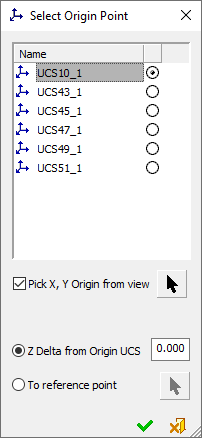
Pre-Defined UCS Origin Point:
From the Select Origin Point dialog, select the predefined UCS that represents the origin point of the LOH/TOH.
The X and Y axis orientation are defined according to X/ Y direction of the drawing sheet and the Z direction is defined by the analysis direction and view projection.User-Defined Origin Point:
In addition to selecting a predefined UCS, you can also set a user-defined origin point in the view, using the options below.
Pick X, Y Origin from view
When this checkbox is marked
 , the Pick X, Y Origin from view enables the selection of a user-defined origin point for the LoH/ToH.
click the
 button to pick the X,Y origin point on the view. The default is the selected UCS X,Y point relative to the view projection.
The Z origin can be defined (using the radio buttons below) either as a delta value or by picking a reference point.
Default = OFF
Z Delta from Origin UCS
Set the Z origin of the reference point as a delta value from the Origin UCS.
This is the default option.
Default = 0.To Reference Point
Set the Z origin of the reference point by picking a reference point on a view perpendicular to the view on which the ToH or LoH are created.
Click the
button to pick the Z origin reference point.Notes:
-
Irrespective of which method is used to select the origin point of the LoH/ToH, the selected Origin UCS is always displayed.
-
If a new point is picked after a point was selected, only the new point is displayed.
-
The user-defined point is associative and the LoH/ToH data is updated accordingly.
-
If the selected point is deleted then the LoH/ToH works with the last known value of the selected point.
-
-
From the Select Origin Point dialog, the required origin point of the Label of Holes and click
 .
.In this step, the system runs the hole analysis procedure on the part. The Set the Table Location
button is automatically selected in the Table of Holes dialog. At this stage, if required, you can pick the location of the table of holes.
Notes:
-
The following parameters in this dialog can be defined at any stage in the TOH creation process:
- TOH Options
- TOH Title, Style & Location
- Column Header/Text Style & Header Location -
The buttons in the TOH Data Editor section can only be accessed after you have positioned the TOH in the drawing.
-
When editing the TOH, all the parameters in this dialog are available, except for the TOH Type dropdown list in the TOH Options section.
-
-
In the Table of Holes dialog, click on the Table of Holes Settings
button. The Table of Holes Settings dialog is displayed.
Use this dialog to set the parameters which are used to identify holes and to create groups of similar holes.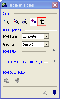
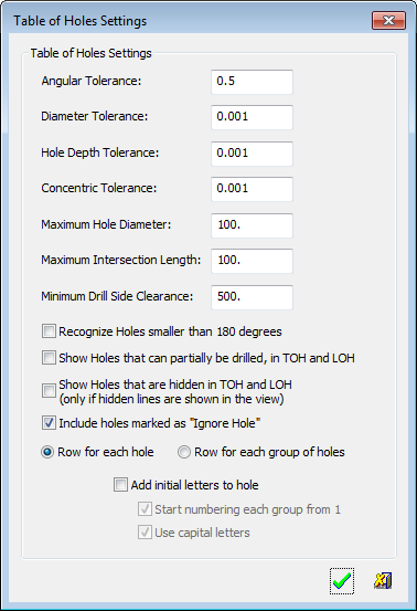
Notes: The Table of Holes Settings
button, can only be defined during the creation of the TOH. It is therefore grayed out (inactive) during the editing procedures of the TOH. (The Define the Origin Location behaves in the same manner).
The settings displayed in this dialog are derived from the default settings defined in the Tables of Holes Preferences and can be only be changed during the creation of a new TOH. -
In the Table of Holes Settings dialog, set the parameters as required. See the Tables of Holes Preferences for parameter descriptions. Click OK
. -
If required, click on the Sketch Holes Selection
button to define new holes directly in the TOH by using Sketcher entities (points and/or circles) in the active view (the view from which the TOH was created). These new holes do not need to be created in the model and the model is not updated (the new hole(s) exist only in the TOH). Sketch holes can also be added later, when editing the Table of Holes. For additional information, see Defining Sketch Holes in the TOH.Note: For other ways of defining new holes, see Defining "Undefined" Holes.
- Click on the drawing to locate the TOH. The system displays the table of holes, for example:
After it has been created, a Table of Holes can be edited in a number of ways.
|