|
|
Cut Lifter  : Options and Results


Access: Open this function from one of the following locations:
-
Select Mold Design > Lifter > Cut Lifter from the menu bar.
-
Select Lifter > Cut Lifter from the Mold Design Guide Toolbar.
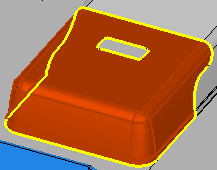
Cut a lifter by active and parting surfaces.
After adding the lifters, the placed lifters are automatically cut and the system creates the relevant pockets in the core and cavity.
Required Step 1 
Pick the component to be cut.
The following parameter is displayed:
|
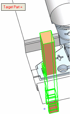
Target Part |
This parameter displays the name of the selected component. The parameter is displayed in red when it is empty (before a part is picked or if you clear the selection). After a part has been picked, the parameter is grayed out and displays the name of the selected component. For example:
Note: After selecting the component, the next step is automatically displayed. You can view the grayed out Target Part label (with the name of the selected component) by re-entering the first step in the function. |


When the required component has have been selected, the system displays the next step in the function.
Required Step 2 
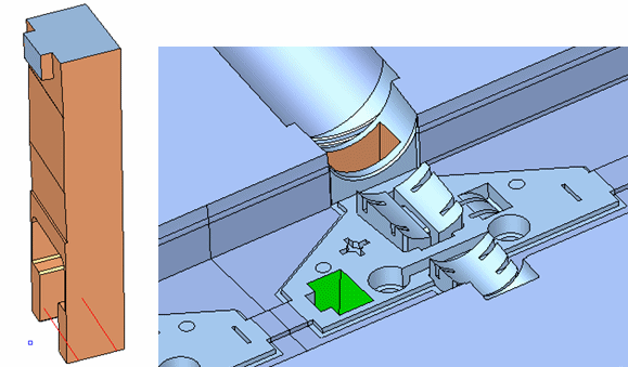
Pick at least one face (see the options below) to cut the lifter; the selected face should be fully or partially contained by the component body.
The following parameters are displayed; to improve clarity, the components selected in step 1 are displayed in wireframe mode in this step.
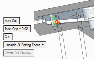
Set the parameters.
|
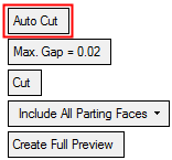
Auto Cut |
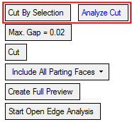
This is a toggle option Auto Cut / Cut By Selection that enables you to control the faces cutting the selected lifter.
Parameters:
Note: The selected face(s) must be active and fully or partially contained by the lifter component body. |
|||||||
|
Max. Gap |
This parameter controls the cut tolerance. The initial default tolerance value is as defined in the Preferences. See the same Preference also for the tolerance range. |
|||||||
|
Cut / Import |
This is a toggle option Cut / Import which determines whether the components selected in step 1 are cut or have a face imported to them.
|
|||||||
|
Include All Parting Faces |
This is a dropdown list that enables you to detect with which faces to cut the lifter.
|
|||||||
|
Create Full Preview |
Create a full preview showing the result of the Cut Lifter operation, based on the selected faces and the above parameter settings. |
|||||||
|
Start Open Edge Analysis |
This parameter is displayed if Cut By Selection was used and at least a single face was selected. Analyze and show the open edges on the selected parting faces by marking them in yellow.
|

Optional Step 1
Cut by undercut extension. Pick the cutting faces.
This option is used to identify the undercut faces (in the work file). These faces are automatically selected the first time you enter this stage. You will then be able to unselect faces or add new faces to the selection (from the work part only).
Flip the arrow direction if necessary.
The lifter is then cut by the selected faces.
Press OK ![]() or Apply
or Apply ![]() in the Feature Guide to complete the function.
in the Feature Guide to complete the function.
The components selected in step 1 are cut by the faces selected in step 2.
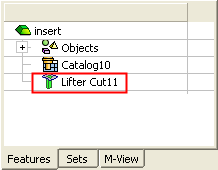
When completed, the Lifter Cut feature will appear in the Feature Tree as follows:
Notes:
-
If instances exist and may get cut by different faces, they are cut according to the first handled instance.
-
New split directions are created in the components cut by the work part faces. A split face attribute is assigned to any face that was created as a result of being cut with a split face in the work part.
-
-
Components holding these faces are attributed as "active parts" and are displayed in the Parting Tree.
-
The new split direction has the same direction and color as the parent split direction in the work part.
-
|