|
|
Cut Active  : Options and Results

Access: Open this function from one of the following locations:
-
Select Mold Design > Tools > Cut Active from the menu bar.
-
Select Parting > Tools > Cut Active from the menu bar.
-
Select Die Design > Tools > Cut Active from the menu bar.
-
Select Cut Active from the Mold Design Guide Toolbar, Parting Guide Toolbar or the Die Tool Design Guide Toolbar (DieDesign).
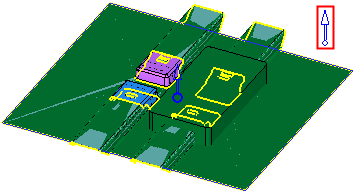
Cut a part by active and parting surfaces of an opening direction.
This function enables you to select a plate (stock) and then to select parting faces (which may be from different parts). The system then automatically stitches the selected parting faces and then either cuts the stock by these parting surfaces, or imports the parting faces to the plate part.
Required Step 1 
Pick a plate (stock) to be cut by the parting faces (or select the part from the Assembly Tree).
The following parameters are displayed:
|
|
|
|

A dropdown list displays the following options:
|
Pick Target Part |
Pick the target part to be cut. The Target Part field displays the name of the selected part. The parameter is displayed in red when it is empty (before a part is picked or if you clear the selection).
After a part has been picked, the parameter is grayed out and displays the name of the selected component. For example:
|
||||
|
Pick Target Sub-Assembly (Export to New Part) |
Pick a target sub-assembly to be cut. This is exported to a new part upon which the cut operation will be performed.
The Target Assembly field displays the name of the selected sub-assembly, and operates similarly to that of the Target Part in the previous option. The New Part Name field displays the name of the new part for the cut operation. |

In the examples below the picked plate is a stock. The plate can be picked using one of the following methods:
-
Pick the plate (object) from the Graphics Area.
When the object is picked, the function immediately moves to the 2nd step and the picked object is displayed in wireframe mode.
-
Select the part from the Assembly Tree.
When the part is selected, it is highlighted and the part name is displayed in the Target Part parameter. To move to the 2nd step of the function, either press the 2nd step icon ![]() in the Feature Guide, or press <exit><exit>.
in the Feature Guide, or press <exit><exit>.
Notes:
-
A non-activated assembly part can be selected.
-
You can switch the selection from an object (in the Graphics Area) to a part (in the Assembly Tree) and vice versa.
-
If a part from the tree is selected:
-
-
The activeactive object in this part (if it exists) is selected. If it is hidden, it is now shown.
-
If there is no active object and no objects at all in this part, no selection takes place.
-
If there is no active object, but objects exist in this part, the first visible object (in the object list) is selected. If it is hidden, it is now shown.
-
An object with an cutting object attribute cannot be selected.
-
-
When editing the feature, you cannot use the tree.
Required Step 2 
Pick the parting faces by picking a split direction (any attached parting faces will be selected) and then press exit. These parting faces will cut the stock that was picked in the 1st step.
Note: In this step, the object picked in the 1st step is displayed in wireframe mode for clarity - so as not to obstruct the display.
Note: The parting faces may belong to multi-lump bodies, solids containing several distinct solid parts.
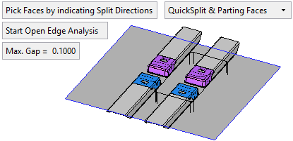
The following toggle parameters appear: Pick Faces by indicating Split Directions / Free Selection:
|
Pick Faces by indicating Split Directions |
Pick the parting faces by indicating split directions. In this case, the split directions must have attached parting faces (the attached parting faces will be selected). This option can only be used if split faces exist in the assembly. If there are no split faces in the assembly, nothing can be picked (as there are no split directions); in this case, toggle to the Free Selection option. Using this method from the Graphics Area:
Using this method from the Parting Tree, the following popup menu options are available from the appropriate parting surface node:
The following dropdown list of options are displayed when Pick Faces by indicating Split Directions is chosen:
Note: If a QuickSplit direction that was selected for a Cut Active operation, was changed, the active part that was created will be marked for update. |
||||||
|
Free Selection |
Pick the parting faces using the normal selection methods. The following toggle option is displayed when Free Selection is chosen:
|
In addition, the following parameters are also displayed:
|
Start Open Edge Analysis |
Analyze and show the open edges on the selected parting faces by marking them in yellow.
|
|
Max Gap |
Enter the stitch tolerance used to stitch the parting faces selected in the 2nd step. The initial default tolerance value is as defined in the Preferences. See the same Preference also for the tolerance range. Changes to the tolerance will not be reflected on the screen until the Preview button is pushed. |
Required Step 3 
Either cut the object selected in the 1st step by the parting surfaces selected in the 2nd step, or import the parting surfaces to the object.
|
|
|
Note: As the function moves into this step, the system automatically stitches the parting faces selected in the 2nd step according to the Max. Gap parameter value (see above).
The following toggle parameters appear: Cut / Import which determines whether the object selected in the 1st step is cut or has parting surfaces imported to it.
|
Cut |
The object selected in the 1st step is cut by the parting surfaces selected in the 2nd step. This is the default option. See Cut Operation Details.
When the Cut option is selected, additional parameters are available; see Cut Parameters, below. |
|
Import |
The parting surfaces selected in the 2nd step are imported to the object selected in the 1st step.
|
Cut Parameters
The following parameters are displayed if the Cut toggle option is selected:
|
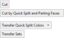
Cut by QuickSplit and Parting Faces / Cut by Parting Faces Only |
This is a toggle option:
|
||||||
|
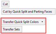
Transfer Quick Split Colors |
This is a dropdown list with the following options to control the transfer of colors to the cut part:
|
||||||
|
Transfer Sets / Don’t Transfer Sets |
This is a toggle option to control the transfer of sets (in which the faces take part) to the cut part:
|
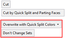
When editing the Cut Active feature, the last two parameter options change to the following:
|
|
|
|
|
Overwrite with Quick Split Colors |
This is a dropdown list with the following color transfer options:
|
||||||
|
Overwrite Sets/ Don’t Change Sets |
This is a set update toggle option:
|
When editing the Cut Active feature, a change will only affect newly cut faces.
Cut Operation Details
When using the Cut option, the object selected in the 1st step is cut by the parting surfaces. In this case you need to indicate the side to be removed by using the directional arrows. You can flip the direction by clicking the arrow.
Note: If, for some reason, the Cut operation fails, the resulting action depends on whether the parting faces consist of single or multi-lump volume bodies:
-
Single lump volume body: The Import operation is automatically performed and an appropriate message is displayed.
-
Multi-lump volume bodies: In this case, the system recognizes the "main parting faces" of the multi-lump bodies. The following outcomes are possible:
-
-
If the Cut operation fails due to the main parting faces, the Import operation is automatically performed and an appropriate message is displayed.
-
If the Cut operation fails due to one or more of the other ("minor") parting faces, the Cut operation is still performed, however, the problematic minor parting faces are imported to the object.
-
|
Example of multi-lumps. The system recognizes the main parting faces. |
Successful Cut operation by the main and minor parting faces. |
|
|
|
In this example, some of the minor parting faces (shown in red below) failed in the Cut operation and these were imported to the object.
Press OK ![]() or Apply
or Apply ![]() in the Feature Guide to complete the function.
in the Feature Guide to complete the function.
When completed, the Cut Active feature will appear in the Feature Tree as follows:
|
|
Notes:
|
|