|
|
Merge/Unmerge Wires  : Options and Results
![]()
![]()

Access: Open this function from one of the following locations:
-
Select Wireframe > Modify Curves > Merge/Unmerge Wires from the menu bar.
-
Select Curves > Merge/Unmerge Wires from the following Die Design Guides: Strip Design.
Merge several wire frame bodies into one body (for both 2D and 3D entities), combining composite curves into one wire-body and more. Unmerge performs the opposite operation. This ultimately enables the fast creation of faces.
Required Step 1 
-
Pick the entities to be merged and set the parameters as appropriate. The following parameters are displayed:
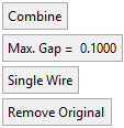
Parameters
Combine / Merge
This is a toggle option: Combine / Merge.
Combine
This operation combines two or more bodies without changing the geometry (meaning the number of edges in the combined body will be equal to the sum of the edges on the separate wires).
The Combine option closes gaps that are less than 0.1 mm. For example, when selecting a wire that contains two curves with a gap of up to 0.1mm, the result will be adjoined. If the gaps are more than 0.1mm, they will not be healed (the result will remain the same as the original).
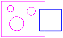
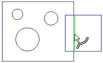
ExampleExampleIn the example below, the two separate sketch entities consist of numerous edges (note the cursor symbol) and can be selected separately.
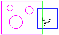
In the Combine option, the edges are not changed topologically and remain in their original state (note the cursor symbol). The resulting curves depends on whether the Single Wire or Multi Wires option was used (see below).
Merge
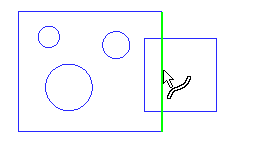
When Merge is selected, intersecting curves are merged. However, merging two intersecting edges creates a new vertex at the intersected point and the original edge is split. If overlapping exists between two or more edges, the overlapped area is removed.
ExampleExampleIn the example below, the two separate sketch entities consist of numerous edges (note the cursor symbol) and can be selected separately.
After the Merge operation, the edges are split at the intersection points (note the cursor symbol). The resulting curves depends on whether the Single Wire or Multi Wires option was used (see below).
Max. Gap
Enter the maximum gap tolerance allowed when merging the wire bodies.
Single Wire / Multi Wires
This toggle option enables the creation of single or multiple wire bodies.
Single Wire
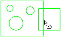
When numerous entities are selected, they are defined as a single wire (the group of entities is regarded as one entity). This is illustrated below where pointing to one of the wires (note the cursor symbol) highlights all the entities in the single wire.
In this case, the result is the same irrespective of whether the Combine or Merge parameter is used.
Multi Wires
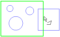
When numerous entities are selected, they are defined as a multiple wires (the group of entities is regarded as multiple entities). This is illustrated below where pointing to one of the wires (note the cursor symbol) highlights only the relevant entity.
In this case, the result differs depending on whether the Combine or Merge parameter is used.
If the Combine parameter is used, the result is as shown below (each entity is a separate wire).
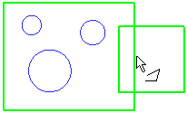
If the Merge parameter is used, the result is as shown below (intersecting wires are regarded as a single entity).
Remove Original / Keep Original
This is a toggle option.
Remove Original
Delete the originally selected entities.
Keep Original
Keep the originally selected entities.
-
Click OKOK
 or ApplyApply
 in the Feature Guide to complete the function.
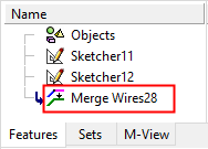
When completed, the Merge Wires feature(s) will appear in the Feature Tree.

|