|
|
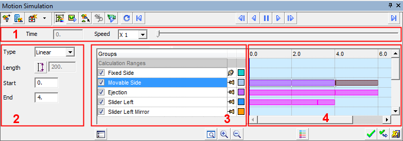
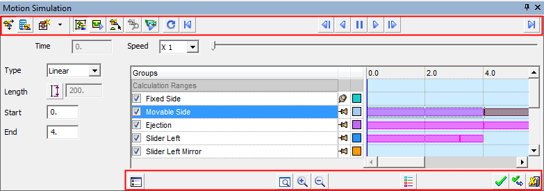
Motion Simulation: Dialog Structure
The Motion Simulation dialog contains the following elements:
Dialog Data Areas
The Motion Simulation dialog contains the following data areas:
|
1 |
Motion Control |
This section of the dialog consists of:
|
||||||
|
2 |
Motion Parameters |
Define the type of motion to be performed by selecting the option from the dropdown list, and setting its parameters. |
||||||
|
3 |
Groups List |
The list of defined motion simulation groups. This list cannot be edited from the dialog. It is inherited from the Groups Tree tab. While in collision mode, to the left of each Group name is a checkbox that enables you to mark the whole group to be Considered or Ignored in Collision Mode (checked means Consider). This is the same as marking each item in a group in the Groups Tree with either the To the right of each Group name is a pin and a color box. The pin is used for locking
The default color of each group is defined in the Preferences; these colors are presented when using the Group Color option. |
||||||
|
4 |
Timeline Grid |
The grid graphically represents a motion of a 'motion simulation group' in time. The scale in seconds is shown on top of the grid. The default scale span is according to the Grid Parameters definition. A motion of a (motion simulation) group is represented by a bar in the row corresponding to it in grid. The bar's left end corresponds to the beginning of the motion while the bar's right end corresponds to the end of the motion. Any motion simulation group can have any number of bars next to it (i.e., more than one motion along the timeline); however, bars (i.e., motions) cannot overlap per single motion simulation group. |
 (Consider) or
  (Ignore) icon.
 and unlocking
  groups.
Dialog Buttons
The Motion Simulation dialog contains the following buttons:
|
|
This is a toggle button Free Motion / Motion by Collision Analysis that enables you to select the simulation mode.
|
||||||||
|
|
Calculate Motions: Calculate all the motions that are not calculated or are calculated but not updated. This option is only available in Motion by Collision Analysis mode. For additional information, see Calculation Motions. |
||||||||
|
|
Interference Check: This is a dropdown list of options for checking interference.
|
||||||||
|
|
This is a toggle button Original Color / Group Color that enables you to select in which color the components are displayed while in the Motion Simulation tool:
|
||||||||
|
|
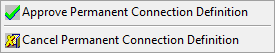
Set Permanent Connections: This option enables you to select various geometrical entities to make connections between motion simulation groups. You can define geometrical relations such as coincident, concentric, and tangent that permanently exist between faces of various components. Permanent connections are useful in cases where a motion simulation group should be directed along a certain trajectory, yet guiding components (such as rails, leading pins, and bushings) do not exist. For additional information, see Set Permanent Connections. To exit this mode, right-click in the display area to display the following approval options and select the appropriate option:
|
||||||||
|
|
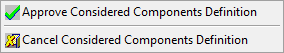
Define Considered Components in Collision Mode: This option is used to exclude components from collision detection in order to run a more limited analysis that doesn't involve all components. (By default all components except unassigned and excluded components participate in collision detection). This option interacts with the Collision column in the Groups Tree, but also allows selection from the screen. The selection changes the state in the column. For additional information, see Define Considered Components in Collision Mode. To exit this mode, right-click in the display area to display the following approval options and select the appropriate option:
|
||||||||
|
|
Analyze Collision: This option is only available if a collision was detected. The option is automatically invoked after a Calculate Motions operation, if a collision was detected. For additional information, see Analyze Collision. |
||||||||
|
|
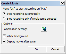
Create Movie: Records the graphic area while the simulation is running. The recording starts as soon as you click Play
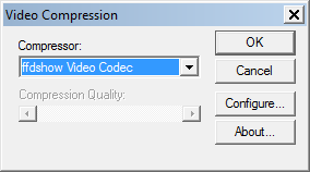
To set a specific video compression, press the Video Compression
|
||||||||
|
|
Repeat: Runs the simulation again. The Repeat button is enabled only when a simulation is not running or is paused. |
||||||||
|
|
Go to Start: Jumps to the start of the simulation. |
||||||||
|
|
Previous Step: Moves the simulation one step (as defined in the settings) backwards. |
||||||||
|
|
Play Backwards: Starts the simulation backwards. |
||||||||
|
|
Pause: Pause the simulation. |
||||||||
|
|
Play: Starts the simulation. |
||||||||
|
|
Next Step: Moves the simulation one step (as defined in the settings) forwards. |
||||||||
|
|
Go to End: Jumps to the end of the simulation. |
||||||||
|
|
Settings: This displays a dialog enabling various options to be defined. For additional information, see Settings - below. |
||||||||
|
|
Zoom All: Zoom to display all defined areas of the grid display. |
||||||||
|
|
Zoom In: Increases the grid display by 50%. Maximum zoom is about 1/200 of the grid's end time. |
||||||||
|
|
Zoom Out: Decreases the grid display by 33%. Minimum zoom is about the size of the grid's end time. |
||||||||
|
|
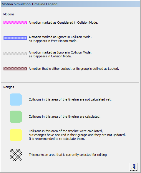
Legend: This displays the Motion Simulation Timeline Legend dialog detailing the meaning of the various motion and range colors. For additional information, see Legend - below. |
Approval Options:
In additional to the dialog specific buttons listed above, the following approval buttons are also displayed:
|
|
OK: Accept the changes, perform the operation, and close the current dialog/task. |
|
|
Apply: Accept the changes, perform the operation, and keep the current dialog/task open. |
|
|
Cancel: Cancel all changes and close the dialog/task without saving the settings. |
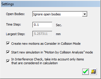
Settings 
Pressing the Settings ![]() button displays the following dialog enabling various options to be defined:
button displays the following dialog enabling various options to be defined:
|
Open Bodies |
This is a dropdown list that enables you to select either to ignore or consider open bodies during the simulation. |
|
Time Step |
With each time step the motion simulation group moves along the predefined trajectory, while the system looks for collisions, and calculates the group locations. A very small time step may result in long calculation times; a very large time step may result in potentially missed collisions since small features may be overlooked. The default value is 0.1 seconds. |
|
Largest Step |
This item calculates the largest distance step created by the time step that was defined (which means – what is the distance traveled in the defined time step in the fastest motion on the timeline). The distance is grayed out and displayed in mm or inch based on the units of the assembly. If there are no motions defined yet, or there are only circular motions, this field is empty. |
|
Create new motions as Consider in Collision mode |
This option determines the default for new motions. When selected, new motions will be created as Consider in Collision mode. If this option is checked off, they will be defined as Ignore in Collision mode. The default is selected. This setting is kept throughout the system. |
|
Start new simulation in "Motion by Collision Analysis" mode |
When selected, this option determines the default for new sessions (one per assembly usually). The default is selected. This setting is kept across sessions (but only used for the first time for each new simulation unless all saved analyses are deleted). |
|
In Interference Check, take into account only items that are considered in calculation |
When selected, only items that are marked in the tree as Consider will be considered in the interference check. The system also considers the checkboxes near the groups in the Calculation mode (taking into account the position on the timeline – meaning the checkbox settings for the relevant range). This is done in both Free Motion and Motion by Collision Analysis modes so that the results are always the same. The default is selected. |
Legend 
This displays the Motion Simulation Timeline Legend dialog detailing the meaning of the various motion and range colors.
|