|
|
Nesting > One Part  : Options and Results

Access: Open this function from one of the following locations:
-
Select Die Design > Nesting > One Part from the menu bar.
-
Select Nesting > One Part from the following Die Design Guide: Die Strip Design Guide.
Create nesting for a single part. This function enables you to create additional instances of one forming shape and place them in the X direction of the active UCS of the strip sub-assembly.
The procedure below describes the steps required for the Nesting operation of one part. This includes selecting the 2D wire body and defining the nesting parameters, such as the minimum distance between the parts in the strip, the rotating angle, the number of progressions and more. The system displays the predefined nesting parameters, strip width, minimum distance and more.
Required Step 1 
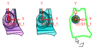
- Pick the Blank (2D wire body) from the forming shapes sub-assembly. The blank can be any Forming Shape that has at least one shown composite curve or sketch.
- ExitExit the step.
Required Step 2 
- Define the nesting parameters. The nesting preview displays the selected blank multiplied by four along the strip.
The first instance of the blank is placed so that its Work CS (Coordinate System) is on the active UCS of the strip sub-assembly. Additional instances of the first shape are shown spread in the X direction of the active UCS of the strip sub-assembly, so that the distance in the X direction between every two parts is the Min. Distance. The blanks are displayed bounded by bounding box lines.
The following parameters are initially displayed:
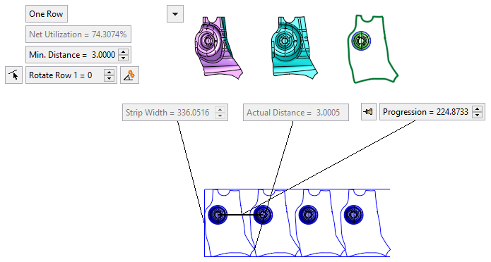
One Row
This is a toggle button One Row / Two Rows that enables you to perform nesting on one part containing one or two rows.
One Row
Perform nesting on a part containing one row. The displayed parameters are as shown in the example above.
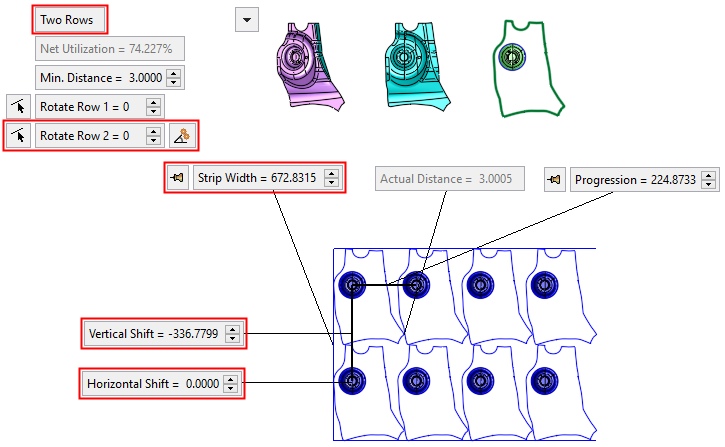
Two Rows
Perform nesting on a part containing two rows. The selected blank multiplied by four along the strip.
The first two instances of the blank (the first instance on each row) are placed so that their Work CS's are shifted to +/- Y direction with reference to the active UCS of the strip sub-assembly. The Progression value remains as it was in one row. The shift in the Y direction conforms to the Min. Distance value.
The additional instances of the blank are spread in the X direction of the active UCS of the strip sub-assembly, so that the distance in the X direction between every two parts is the Min. Distance.
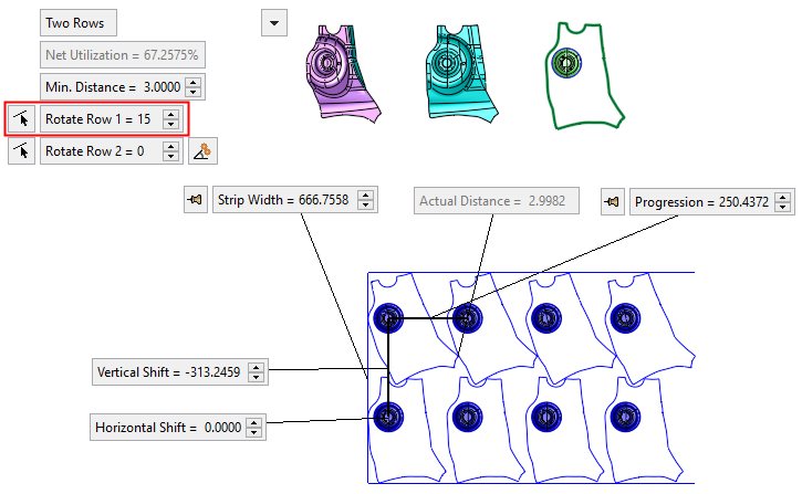
The displayed parameters are as shown in the example below:
Example:Example:In the image below, the additional/changed parameters are highlighted.
Net Utilization
The net nesting utilization according to the selected shape and parameter settings. This parameter is system calculated (read only) and is the ratio between the area of the blank (the gross area including holes) to the strip area (in percentages).
Min. Distance
The minimum distance between the nested parts.
The Actual Distance value between the parts cannot be less than this "Min. Distance" value.
Valid inputs are >= 0.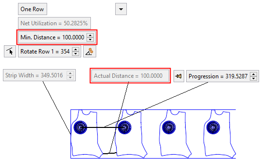
If the Progression parameter is in Fixed mode (see below), the "Min. Distance" parameter is dimmed.
Rotate Row
This parameter controls the rotation of the blanks around the Z axis of their Work CS. The default value is 0.
Rotate Row 1 controls the rotation of the blanks in row 1 around their Work CS; and Rotate Row 2 correspondingly for row 2.
When changing rotation value, the Progression parameter value changes to keep the defined minimum distance.
A Reference Line button
 is attached to this parameter.
Pressing this button allows you to pick a reference line for rotation;
the blanks will rotate so that this reference line is parallel to the
X direction. The reference line can be selected from linear edges/curves
from any component in the assembly. In addition, 2 points can be also
selected for the direction (selected from any component in assembly file).
The rotation angle is displayed in the "Rotate Row" parameter.
The angle is not associative to the reference line.
is attached to this parameter.
Pressing this button allows you to pick a reference line for rotation;
the blanks will rotate so that this reference line is parallel to the
X direction. The reference line can be selected from linear edges/curves
from any component in the assembly. In addition, 2 points can be also
selected for the direction (selected from any component in assembly file).
The rotation angle is displayed in the "Rotate Row" parameter.
The angle is not associative to the reference line.Note: Rotating when the Progression and/or the Strip Width parameter is Fixed, may cause overlapping of the blanks.

Click this button to automatically find the optimal rotation angle that gives the best utilization rate of the strip.
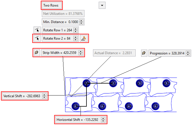
Two Rows: The angle and utilization rate before optimization:
Two Rows: The angle and utilization rate after optimization:
For the One Row toggle option:
This button is displayed adjacent to the Rotate Row 1 parameter and finds the optimal angle for the best utilization rate for that row.
Example:Example: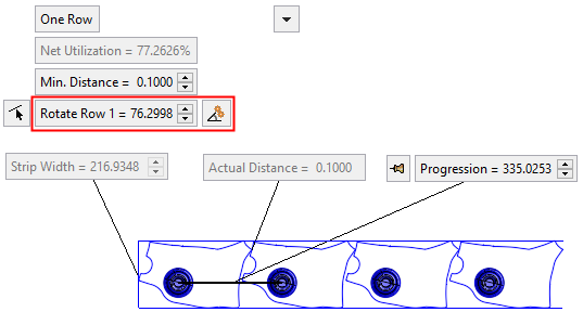
For the Two Rows toggle option:
This button is displayed adjacent to the Rotate Row 2 parameter and finds the optimal angle for the best utilization rate for both rows.
The strip display and the angle in the relevant row parameter are updated accordingly.
Note: This button is only available when the Progression parameter is in a Float state (when the Float
 button is displayed adjacent to the parameter).
Toggle the parameters expand/collapse button
/ to display the following predefined nesting parameters:
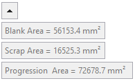
Blank Area
The blank area according to the selected shape and parameter settings.
Scrap Area
The scrap area according to the selected shape and parameter settings.
Progression Area
The progression area according to the selected shape and parameter settings.
Strip Width
This displays the width of the bounding box.
For the One Row toggle option:
This parameter is dimmed (read only).For the Two Rows toggle option:
This parameter is displayed with an attached Fix/Float button (
 /).
By default, the Float button is displayed. When
the "Strip Width" value is manually changed, the Fix
button is displayed. This means that the width value
is not 'associated' with the other parameter values (for example, a change
in the Min. Distance will not
affect the "Strip Width" value).
/).
By default, the Float button is displayed. When
the "Strip Width" value is manually changed, the Fix
button is displayed. This means that the width value
is not 'associated' with the other parameter values (for example, a change
in the Min. Distance will not
affect the "Strip Width" value).To 'activate' the parameter, toggle the Fix button to Float. The preview will jump to comply with the change.
Actual Distance
This displays the actual distance between the blanks. This value is governed by the Min. Distance parameter value; the "Actual Distance" value can be greater than the Min. Distance value (depending on, for example, a manually changed Progression parameter value), however, it cannot be less than the Min. Distance value.
If blank overlaps occur (as a result, for example, of a manually changed Progression value), the "Actual Distance" parameter is shown as 0 and displayed in red.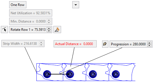
Progression
This displays the distance between the blank's Work CS’s according to the Min. Distance. This value can be changed, with the preview changing automatically.
A Fix/Float button (
/) is
attached to this parameter; by default, the Float
button is displayed.When the "Progression" value is manually changed, the Fix
button is
displayed. This means that the "Progression" value is not 'associated'
with the other parameter values (for example, a change in the Min.
Distance does not affect the "Progression" value).To 'activate' the parameter, toggle the Fix button to Float. The preview will jump to comply with the change.
Vertical Shift
This parameter is displayed when the Two Rows toggle parameter is selected.
This parameter controls the vertical distance between the two rows of blanks on the strip. A negative value can be entered.Horizontal Shift
This parameter is displayed when the Two Rows toggle parameter is selected.
This parameter controls the horizontal distance between the two rows of blanks on the strip. A negative value can be entered.
- Click OKOK
 or ApplyApply
 in the Feature Guide to complete the function. When completed, the new Part appears in the Feature Tree
|